12v RGB LED with Arduino © GPL3+
DESCRIPTION
Introduction
In this tutorial, we are going to learn about how to connect a 12v RGB LED strip with Arduino and how to program to make different color combinations and fading animations.
Pin Out – TIP120
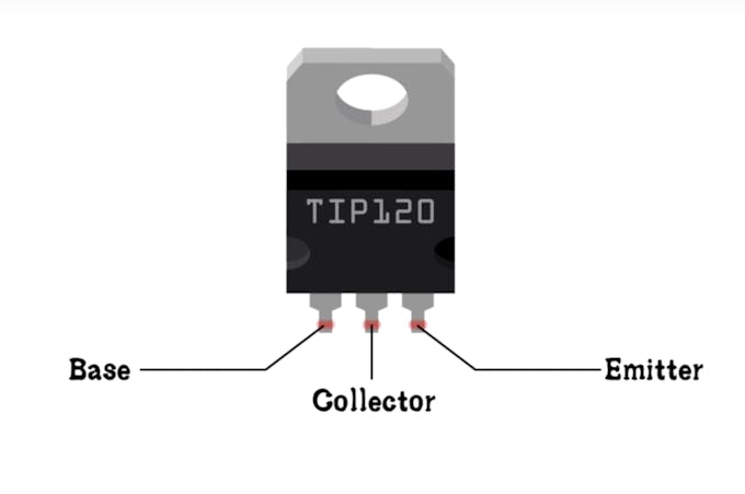
You can use any NPN transistors like TIP120, TIP121, TIP122 of N-Channel MOSFETs like IRF540, IRF 530, based on your application you can change the transistors. the difference is that they have a different collector-emitter current rating. For example, if you are using a large length of RGB LED strip then to drive them you will be needing high current transistors like IRF540 which have Drain Current (Id): 28 Amps. Or if you need only a few LEDs then you can use any other NPN transistors like TIP120 which have Collector Current of 5 Amps continuous and 8 Amps peak
In this tutorial, I am using TIP120 and the pinout diagram is shown below. You can download the datasheet from here.
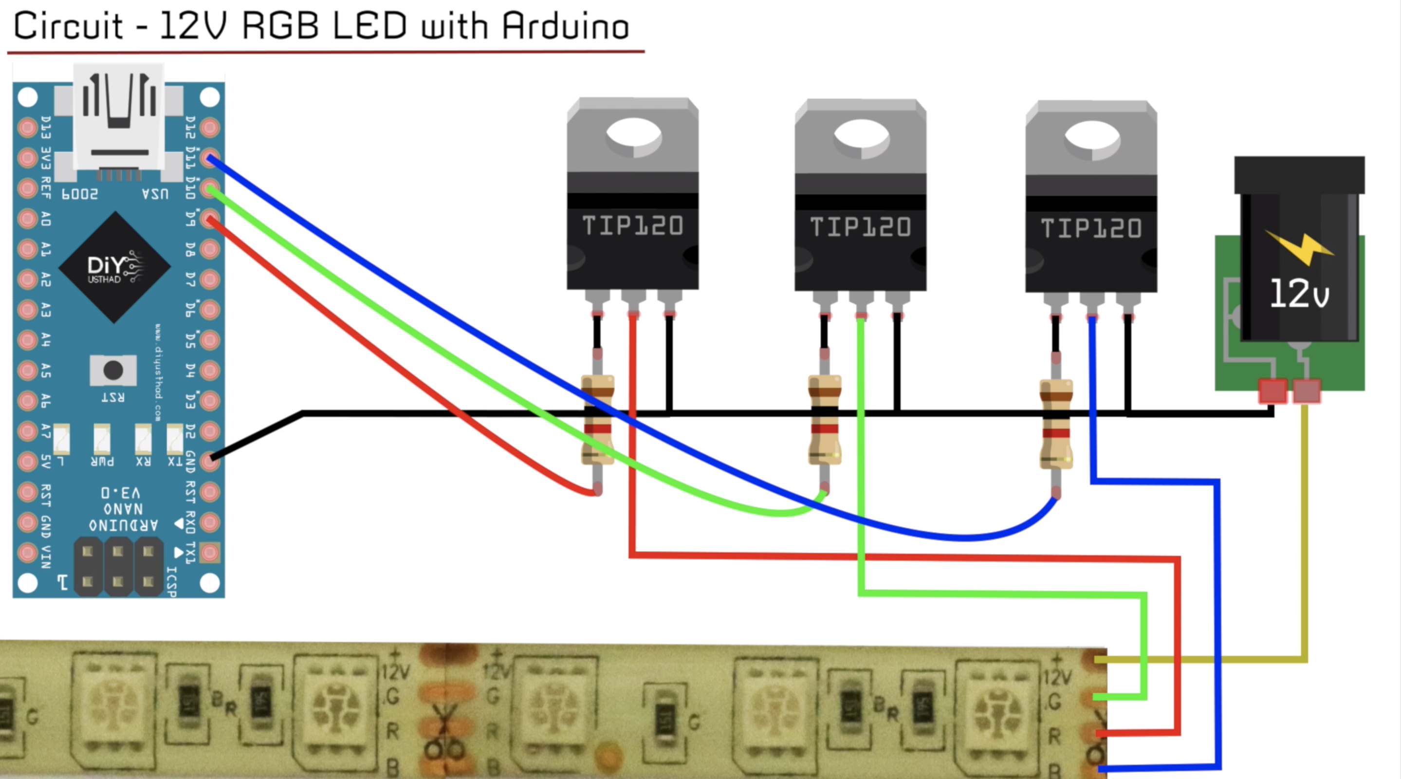
Circuit

- Connect the emitter of all the transistors to the Ground of Arduino.
- Connect the Ground of 12V power supply to the Ground of Arduino.
- Connect the positive terminal of 12V power supply to the 12V pin of RGB LED strip.
- Connect 1 K resistor to the base of the each transistors as shown.
- Connect wires form the digital pins D9, D10, D11 to the other end of the resistors as shown in the circuit diagram.
- Finally connect wires from the R, G and B terminals of the RGB LED strip to the collector (middle pin) if the TIP120 transistors as shown.
Complete Video Tutorial


Introduction
In this tutorial, we are going to learn about how to connect a 12v RGB LED strip with Arduino and how to program to make different color combinations and fading animations.
Pin Out – TIP120
You can use any NPN transistors like TIP120, TIP121, TIP122 of N-Channel MOSFETs like IRF540, IRF 530, based on your application you can change the transistors. the difference is that they have a different collector-emitter current rating. For example, if you are using a large length of RGB LED strip then to drive them you will be needing high current transistors like IRF540 which have Drain Current (Id): 28 Amps. Or if you need only a few LEDs then you can use any other NPN transistors like TIP120 which have Collector Current of 5 Amps continuous and 8 Amps peak
In this tutorial, I am using TIP120 and the pinout diagram is shown below. You can download the datasheet from here.
Circuit
- Connect the emitter of all the transistors to the Ground of Arduino.
- Connect the Ground of 12V power supply to the Ground of Arduino.
- Connect the positive terminal of 12V power supply to the 12V pin of RGB LED strip.
- Connect 1 K resistor to the base of the each transistors as shown.
- Connect wires form the digital pins D9, D10, D11 to the other end of the resistors as shown in the circuit diagram.
- Finally connect wires from the R, G and B terminals of the RGB LED strip to the collector (middle pin) if the TIP120 transistors as shown.
Complete Video Tutorial