MIDI/Arduino Controlled 8-Bit Sound Generator (AY-3-8910)
DESCRIPTION
Build a retro sounding 8-Bit Sound Generator and control it through MIDI.
This design is partly inspired by Chiptune enthusiasts building Arduino circuits to play Chiptune files and some of my own ideas to integrate the sound of early video game consoles into my synth-jam setup.
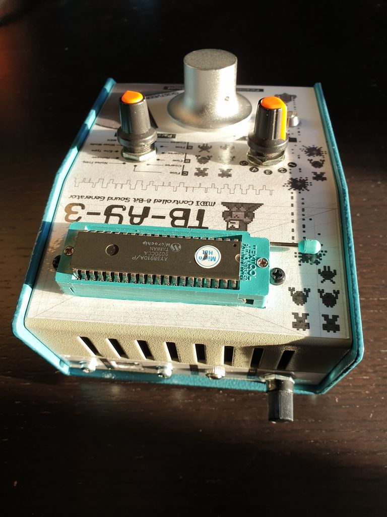
The design is centered around the 1978 AY-3-8910 programmable sound generator. This chip contains three independent square-wave oscillators (great for generating chords), a noise generator, an envelope generator and a mixer. All these functions are fully controllable, but it does comes with a few limitations; the design I am presenting here is meant as an extension to, for example, drum machines/samplers capable of sending MIDI (trigger) notes. This design, called TB-AY-3 (or Techno Box AY-3-8910) sounds best with the release-only type of envelope (i.e. to generate percussion type of sounds), but it does allow you to select other types.
I pre-programmed 8 patches:
The first 5 you can freely edit (Bass drum, Snare drum, Closed hi-hat, Open hi-hat and a bleep sound)
The remaining 3 patches are hard coded (a random bleep sound, an arcade kind of video game sound and a Kraftwerk "pocket calculator" kind of random melody)
You can't save the changes you make to the 5 selectable patches; the intention here is to tweak the sounds on the fly (as they are MIDI-triggered) - often resulting in cool techno patterns.
Important to understand here is that the design is monophonic (only one patch at a time).
Of course, I am including the Arduino code, so feel free to customize the default patches.
Enough intro - let's get started!
Ok, let's summarize the materials you need to build the TB-AY-3. The total cost shouldn't be more than £75,- Definitely search for parts on ebay to get a good deal.
AY-3-8910 - (1x)
40-Pin ZIF DIP IC Socket - (1x)
Arduino Nano - (1x)
30cm Mini USB 5pin Male to USB 2.0B Female Socket Panel Mount Cable - (1x)
Hammond 1456CE2WHBU Sloped Enclosure 146x102x56mm Aluminium Blue/Beige - (1x)
12 Position 1 Pole BBM Break Before Make Rotary Switch - (2x)
Rotary Encoder Module KY-040 Clickable Switch - (1x)
Resistors (metal film 1/4 Watt)
3 x 220 Ohm
3 x 10K
1 x 3K3
1 x 4K7
3 x 8K2
6 x 2K7
12 x 2K2
Capacitors (radial electrolytic, 16V)
1 x 100uF
1 x 10uF
Capacitors (ceramic disc, 16V)
1 x 100nF
1 x 10nF
Potentiometers
1 x 100K (Log), 7mm diameter, 15mm shaft length
Diodes
1 x 1N914
Integrated Circuits (chips) & Sockets
1 x 6N138 (Optocoupler) & 1 x DIL8 socket
1 x 7404 (Hex Inverter) & 1 x DIL14 socket
LEDs & Holder
1 x Common cathode, clear transparency, Tri-Colour LED, 5mm & 1x 5mm chrome holder bezel mount
1 x Red, 3mm & 1 x 3mm black plastic holder bezel mount
DIN Sockets (for MIDI in/thru)
2 x 5 Pin DIN chassis panel mount female socket
VERO board
1 x prototyping copper strip board; 95mm x 127mm should do
Adhesive labels (for printing front panels) & Film
3 x A4 adhesive white sheets
A roll of self adhesive pvc clear film (to put on top of printed labels)


Download the diagram here (zipped and .png). It's split in two parts;
1 (of 2) - This is the Arduino Nano + AY-3-8910 + MIDI In/Thru circuitry
2 (of 2) - This shows the wiring of the two 12-position rotary switches
Note: the rotary switches have an adjustable stop-ring that lets you set the switch to fewer positions (the patch select is to be set to 5 positions and the parameter select is to be set to 11 positions)
Attachments

Download the PCB layouts here. There's a PCB for the Arduino Nano & MIDI circuitry (plus some other components) and there's a PCB for the ZIF socket holding the AY-3-8910.
Download also the wiring to/from selection switches, LEDs, line output, encoder (parameter change), MIDI ports and the AY-3-8910 board.
Attachments

Of course, you also need the Arduino code (or sketch). Download and unzip the file shown here.
Make sure you have the following libraries installed:
MIDI.h (https://playground.arduino.cc/Main/MIDILibrary/)
Encoder.h (https://github.com/PaulStoffregen/Encoder)
Button.h (https://github.com/tigoe/Button/blob/master/Button.h)
Update:
Gary Aylward kindly refactored the code (reducing it by 70%!), which can be found here on github.
Attachments


 33 More Images


If you decide to go with the Hammond 1456CE2WHBU Sloped Enclosure (146x102x56mm), then please print out the attached images on plain white paper. Cut out the labels and use adhesive tape to attached them to the enclosure.
Use these temporary labels to mark all drill holes and metal cut outs.
Remove the temporary labels, drill the holes and cut out the rectangular area so that the ZIF socket fits nicely.
Make sure the enclosure is clean by removing all grubby or moist areas otherwise the adhesive labels, in the next steps, won't stick very well.
Once more, print out, on self adhesive white A4 paper this time, the front panel images.
Cover the print outs with self adhesive pvc clear film and cut out the labels.
Stick the labels over the drilled holes and rectangular ZIF socket area.
Use a scalpel to carefully cut out all areas covering the holes for dials, LEDs, encoder, MIDI, power, output and, of course, the large square accommodating the ZIF socket.
Now it's time to put all panel-mount components in place.
Please have a look at the images showing you the various stages of putting the project together.