AiRobot © GPL3+
DESCRIPTION
The Team
Blaine Ayotte: Full-time graduate student
Tyler Bershad: Full-time engineer
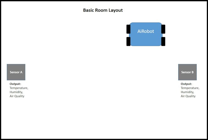
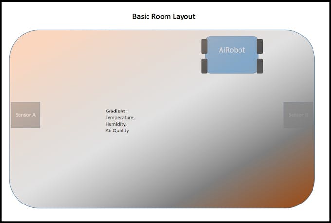
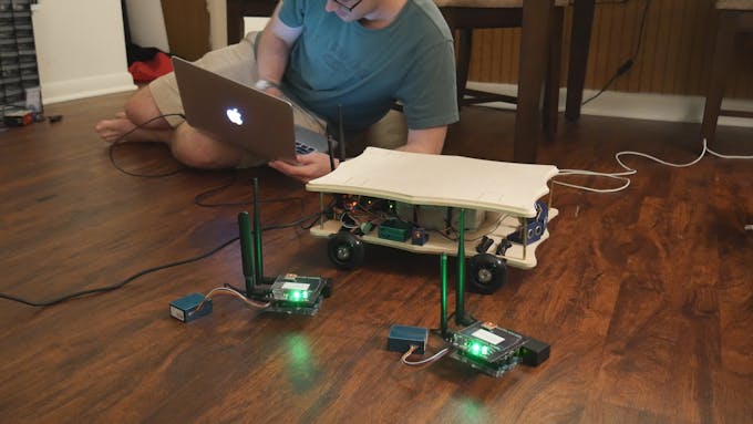
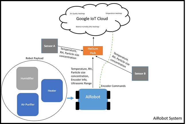
Overview on the AiRobot SystemThe AiRobot system comprises of a group of networked sensors and a robot. Every device has sensors that deliver temperature, relative humidity, and air quality measurements to the Google IoT Cloud by using the Helium platform.
The AiRobot is meant for indoor use in homes. AiRobot support sensors are placed a known distance apart and the robot is placed in a calibrated spot. Once the AiRobot is switched on, it will wander between the AiRobot Support Sensors to collect data. The AiRobot knows where it is by using it's motor encoders.
AiRobot Support SensorsThe AiRobot Support Sensors continuously send temperature, humidity, and air quality information to the Google IoT Cloud through Helium. These Support Sensors are fixed at a known location in a room. This is important to building the several heatmaps.
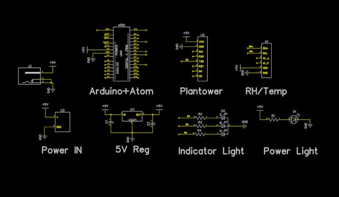
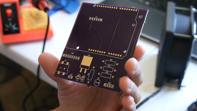
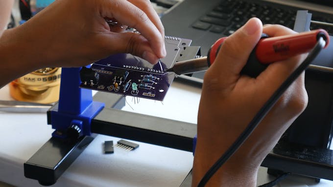
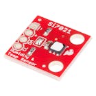
AiRobot Support Sensor SchematicThe AiRobot Sensor schematic above gives insight on its capabilities. The Sensor has LEDs to help notify the user about programming and power activity. The Plantower (PMS5003) is our air quality sensor and the Si7021 is the RH/Temp sensor. J3 is a barrel jack connector, U3 are power input pins, and both are connected to U11 which is the L7805, which has an voltage input range of 7V-35V.
Note: we designed the board for a different SparkFun RH/temp sensor than what the board above was built for. It was an easy wiring fix.
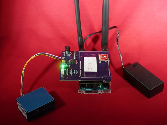
How We Mounted AiRobot Support SensorIf you look closely on the bottom of the Arduino, we utilize the case with M3 screws to mount. We did not have enough time to 3D print an enclosure, so this was a quick, great, option!
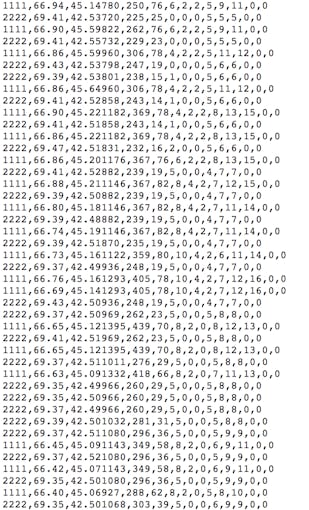
AiRobot Support Sensor Output & Cloud DataThe photo above shows a test example on how data is sent to the cloud. The AiRobot Support Sensor are the lines that start with 2222.
The data is formatted in the following fashion:
SensorName, Temperature, Relative Humidity, PM0.3um, PM0.5um, PM10um, PM25um, PM50um, PM100um, PM1, PM2.5, PM10, nothing, nothing
What's with all those PM's?
PM stands for particulate matter. The PM03um, PM0.5um, PM35um, PM50um, PM100um are particle size ranges per 0.1L air.
PM1, PM2.5, PM10 are measurements of particle concentration measured in standard units (ug/m3).
AiRobotOverview
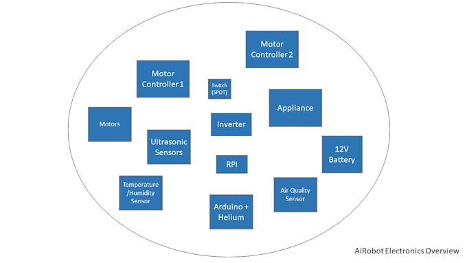
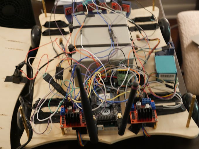
Below is a picture of an overview of the electronics on AiRobot There is alot of stuff going on, right!?
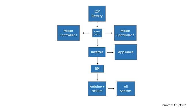
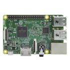
For AiRobot we used an Arduino Mega for data acquisition and movement, Helium for sending data to the google cloud, and the Raspberry Pi to send serial commands to the robot from the google cloud. The picture below shows that process.
AiRobotPower Structure
AiRobot Wiring GuideHere's an interior look at the AiRobot. There is so much stuff going on! We did not have enough time to create a custom PCB to avoid wires traveling everywhere, so we used tape, zip ties, and and whatever we could to keep cables from becoming loose.
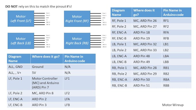
Motors
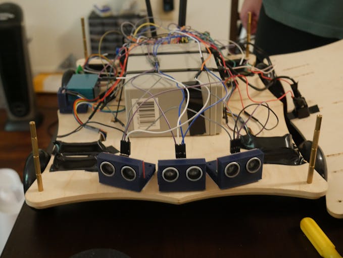
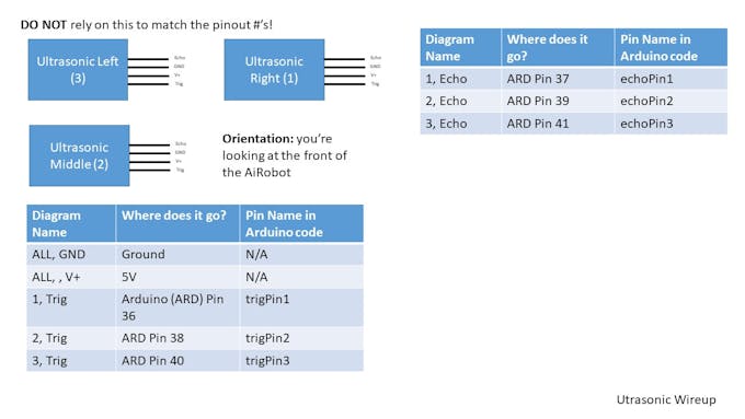
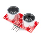
UltrasonicSensors
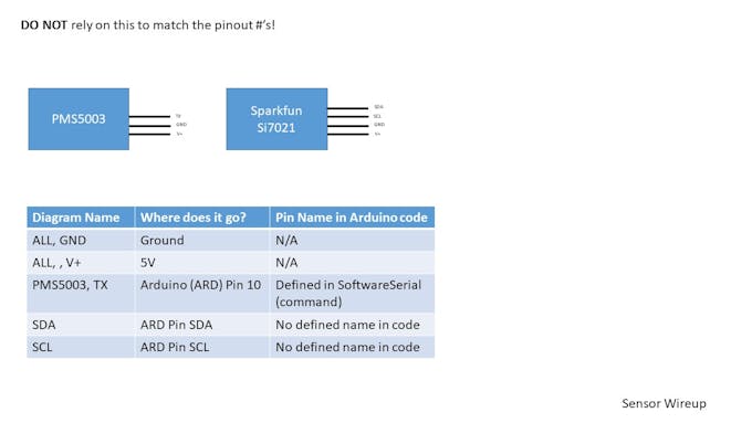
Temperature,RelativeHumidity,AirQualitySensors
AiRobot HardwareMountingand Securing
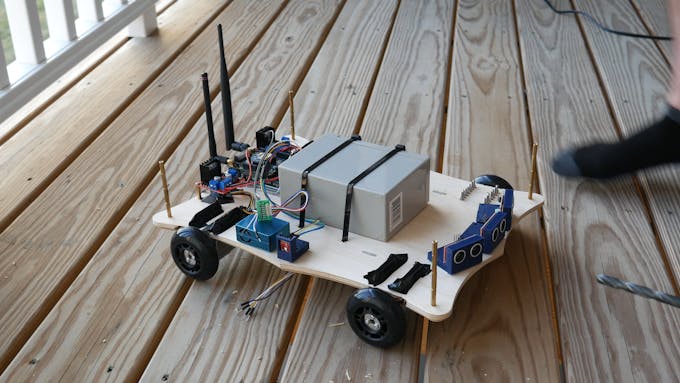
To mount objects to the chassis, we used several different methods: Tape, Screws, standoffs, 3D prints, and zip ties.
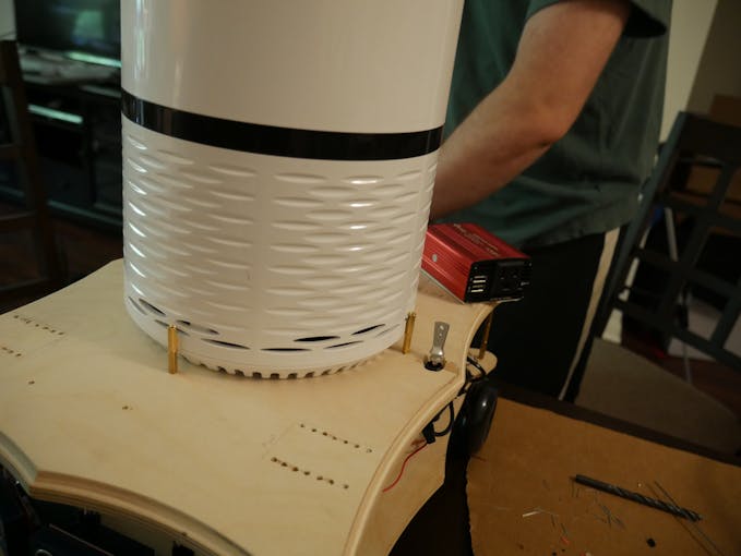
Standoffs
Standoffs were used to sandwich the two wooden plates together and secure objects on the platform (as seen in the photo above). We also used standoffs to mount the motor controllers to the AiRobot Chassis
ZipTies,3D Prints,Screws
We used zip ties to secure the 12V battery to the AiRobot chassis. The 3D printed parts were used to mount the Ultrasonic Sensors and Temperature/Humidity (SparkFun Si7021) to the chassis. The 3D prints had holes for M3 screws to go through, which were secured using a nut on the opposite side.
DoubleSidedTape
We used double sided tape to mount the PMS5003 (Air Quality) sensor, the Inverter, and the Raspberry Pi.
ArduinoMega+ HeliumMounting
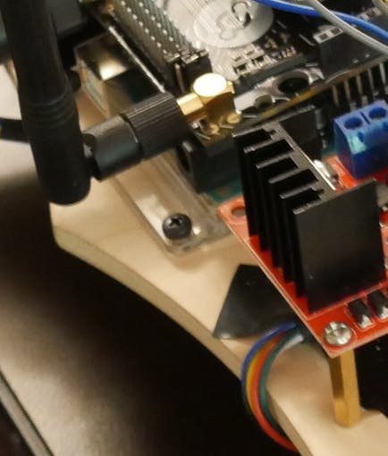
The helium plugs into the Arduino through the pins, which is how it is typically mounted. The Arduino Mega was secured with M3 screws that go through pre drilled through holes on the PCB and case
MotorMounting
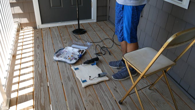
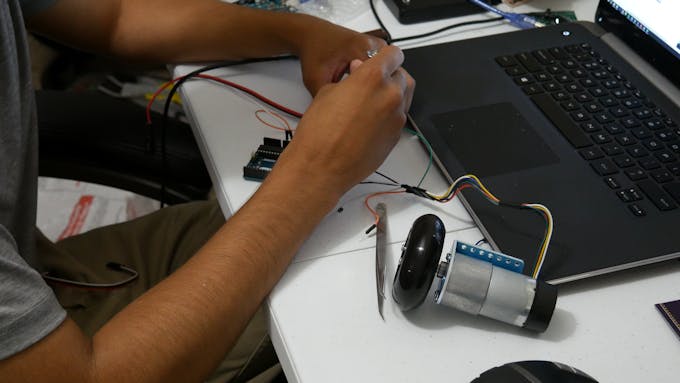
We mounted the motors by pencil marking the L bracket hole pattern on the robot and drilling holes through. It was secured using a nut.
AiRobot Drive Train
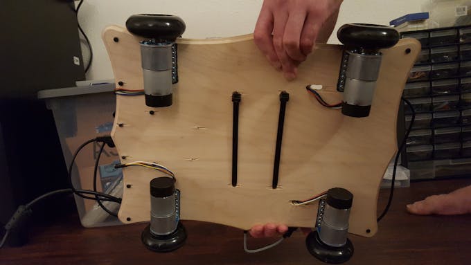
AiRobot was built with 4 wheel drive. We chose 4 wheel drive because we knew that AiRobot would be carrying a heavy payload (>8kg).
All motors are the same model and have the following specs:
Gear Ratio: 131:1
MaxRPM: 80 RPM
MaxTorque: 250 oz-in
Stall Current: 5 A
The wheels are 75mm Polyurethane scooter wheels from Pololu. The wheel diameter is small because we wanted to support heavy loads. Scooter wheels works best on hard wood floors and has a disadvantage on carpet.
Battery ConsiderationsKnowing the power consumption of all the electrical devices we intended to use was important before we purchased a battery. Before building the robot, we created a Power Consumption Table to figure out what kind of 12V battery Ah we needed. To do these calculations, we just used the power equation: P = IV
Helium IoT CoreIn this project we used the Helium IoT Core to get all of our data up to the cloud. The board was easy to use, and worked great! We won't go be creating a tutorial in this section on how to setup the helium to the google cloud, because they already have fantastic documentation on setup!
Here's the helium setup link: https://www.helium.com/dev/hardware-libraries/arduino
We used 3 Helium Atoms with an Arduino adapter to send to 1 Helium channel. All the data goes to 1 file in 1 bucket every 5 minutes on the google cloud.
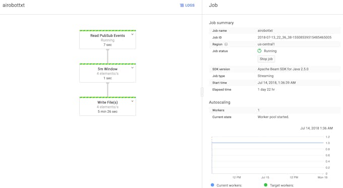
Google Cloud Services ComputationsThe data was added every 5 minutes to our bucket using a dataflow. The Google Cloud platform was used to create a virtual machine to help process our data. This was immensely helpful and allowed everything to be all in one place without being cluttered.
Once the data was uploaded to our bucket we used our virtual machine to process it and create heatmaps. Google Cloud Services has excellent tutorials on how to set up everything from virtual machines to Dataflow jobs and I recommend checking their documentation if you experience difficulty. The link to their tutorials page can be found below:
https://cloud.google.com/storage/docs/tutorials
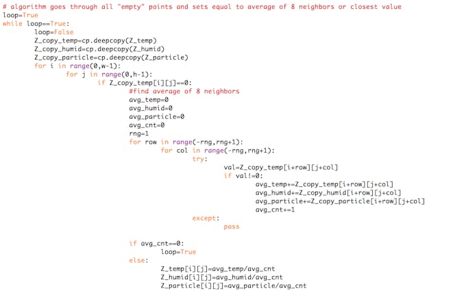
Heatmap CalculationsAfter the data was processed and the encoder information was transformed into displacement we needed to calculate the from a few individual points. To create the heatmaps from a bunch of discrete values we used an iterative approach which can be seen in the python code snippet below (for all code see bottom of page).
Each time through the while loop the unfinished heatmaps for temperature, humidity, and particles are copied. We search through every point in the heatmap array and if there is no value provided either by the robot or the supporting sensors we average the cell's 8 neighbors and set it to that value. If it has no neighbors we ensure to stay inside the while loop. After many iterations the discrete values will be expanded based on averaging and a distribution is created.
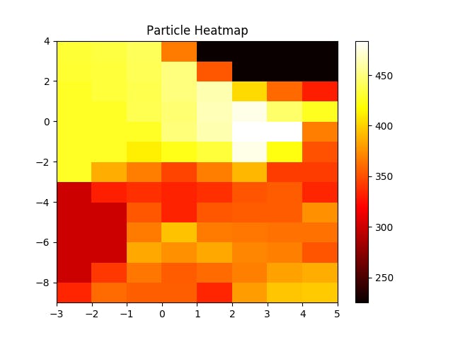
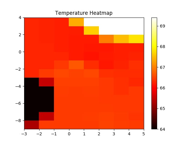
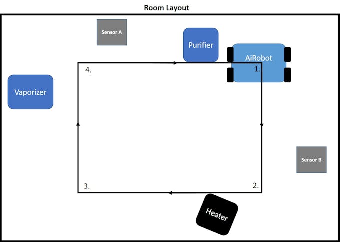
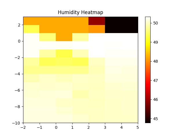
Initial Heatmap TestingIn the heatmap graphs below, the origin of the AiRobot is (0, 0). The entire filled area is the bounds of our defined world. The robot starts of traveling in the positive x direction for 4 units (feet). At location [4, 0] the robot turns 90 degrees and travels to [4, -7]. The robot then finishes the rectangle traveling to [0, -7] and back to [0, 0] in that order. Below are the heatmaps for particles, temperature, and humidity for a sample run.
Heatmap Verification TestingWe wanted to make sure that our heatmap values made sense, so we placed a vaporizer, heater, and air purifier at different known locations in the room.
** In this picture, the AiRobot has sensors on the left side.
**For this testing we used the sensors at the same height as the robot.
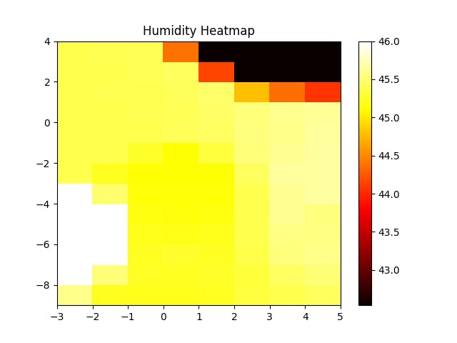
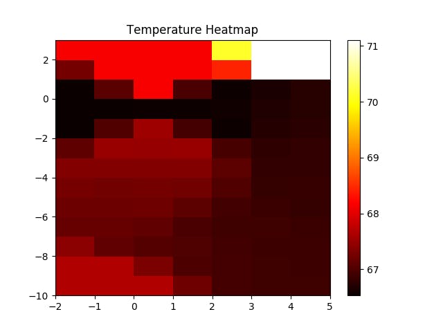
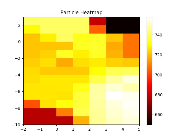
The results of the test were promising and showed our robot was working. The following 3 images are the heatmaps for temperature, particles, and humidity. NOTE: THEY ARE ROTATED 90 DEGREES FROM ABOVE IMAGE
The heater is located in the top right corner of this image which lines up well with the region of white denoting a high temperature value.
The humidifier is located in the bottom right corner of this image which is consistent with our results. We see higher number of particles located in that bottom right corner.
The humidity heat map also agrees with our expected results as the humidifier is located in the bottom right corner. There appears to be roughly uniform humidity for the bottom two thirds of the image.
These three images give us stock in AiRobots ability to measure temperature, humidity, and particle distributions through a room.
Driving to Pollution Source/Region of InterestWith an accurate heatmap the next step is to locate the region of interest and navigate there with the desired appliance. For example, if a region with high concentration of particles was detected an air purifier could be mounted on AiRobot and it would drive to the source. By driving to the source AiRobot is best able to improve air quality or issues. Appliances we used were a humidifier and air purifier. To navigate AiRobot to a spot on the heatmap the distance from Airobot's currently location and the bad spot was calculated. This was calculated on GCS and a txt file of the desired navigation commands was outputted. Our RPi then transferred the commands through serial and directed the robot to its desired location.
Programming InstructionsDue to the massive amount of information, we struggled providing a step by step tutorial on how to fully build all components of AiRobot. But in this section, we hope to provide you some insight on how the programming works! All of our code is attached to this project as well.
The generic structure is laid out as follows:
1) Arduino Mega wanders around room reading encoders, particles sensor, temperature sensor, and humidity sensor. All this data is continuously streamed to the Google Cloud using helium.
2) After enough data is sent to Google cloud our virtual machine processes encoder information and converts it distance. Heatmaps are created using these distance measurements and the sensor values (temperature, humidity, particle concentration).
3) Point of interest is calculated from the heatmaps and serial directions on how to navigate there are calculated from virtual machine and uploaded to Google Cloud.
4) RPi copies directions from Google Cloud and transmits it to arduino through serial. This directs AiRobot to its final position where it stays and runs the desired appliance.
5) Lastly code runs on the virtual machine tracks sensor measurements in AiRobots location to monitor progress of cleaning the polluted area.
Obstacles we encounteredThis project was not easy. We encountered obstacles all along the way. Thanks to all nighters and never giving up, we overcame them.
Some problems we encountered were:
1. Time. This project was an enormous amount of work that was done in a short period of time. We are only a team of 2!
2.Sleep. Towards the submission date, we pulled several all nighters to work hard and overcome all obstacles we had to.
3. PartSelection. Given the time constraints and the complexity of this project, we were forced to make quick decisions about parts
3.a Motor Selection. When choosing the motors to use, we had to theoretically make sure that it was in the spec to carry our intended load. This load is based on alot of things, since we have alot of parts.
4.PowerConsumption. Depending on the appliance you wanted to put on the AiRobot platform, the weight of the unit and the total power consumption increases. When the power consumption increases, it changes our required lead acid battery size, which means much larger % changes in weight. Lead acid batteries are HEAVY!
5.Robot Positioning. We tried GPS - it was not good enough. We tried an accelerometer - it was not good enough. Signal Strength was not good enough. We had too little time to learn IR pattern recognition with a camera. This was an extremely tough obstacle, so we just relied on encoders.
6.Encoders. We had trouble reading all values of the encoders at the same time. This was a very annoying problem. We were forced to rely on encoder data from one wheel.
7. Monitoringand controllingSOMANY THINGS. Very stressful, very difficult. So much code that needed to be written.
Possible Future Improvements to AiRobotWe didn't have alot of time on this project, so we could not make AiRobot perfect. We're very satisfied with the work we completed though! Some future improvements:
1.Moreaccurate Positioning. We believe that this is the hardest part of this entire project. We believe that the IR method that Broomba's use might by the best chance to get this to work.
2.Wander mode. Once we have more accurate positioning, AiRobot can start from anywhere without being calibrated. It can truely walk randomly within a room.
3.AiRobotAppliances. If we were to hack or build the appliances we put on the AiRobot platform, we could customly modify the environment based on the data we receive without having to touch a button.
Codes We're Most Proud OfRobot Code://Libraries
#include "SparkFun_Si7021_Breakout_Library.h"
#include <Wire.h>
#include <Helium.h>
#include <SoftwareSerial.h>
#include "Arduino.h"
#include "Board.h"
#include "Helium.h"
#include "HeliumUtil.h"
//Definitions - Encoder A and B
//Code for pin names
//First digit: R,L for right and left
//Second digit: F,B for front and back
//Third digit: A,B for encoder A and encoder B
#define RFA 18
#define RFB 19
#define RBA 50
#define RBB 51
#define LFA 2 //LFA PIN CHANGED FROM 42 to 2
#define LFB 3 //LFB PIN CHANGED FROM 43 TO 3
#define LBA 48
#define LBB 49
//Definitions - Enable Pins
#define RFE 11 //RFE PIN CHANGED from 2 TO 11
#define RBE 9 //RBE PIN CHANGED FROM 3 to 9
#define LFE 4
#define LBE 5
//Definitions - Motor Poles
#define RF1 26
#define RF2 27
#define RB1 28
#define RB2 29
#define LF1 7
#define LF2 8
#define LB1 32
#define LB2 33
//Definitions - Encoders
int RFval;
int RBval;
int LFval;
int LBval;
int RFpos = 0;
int RBpos = 0;
int LFpos = 0;
int LBpos = 0;
int RFlast = LOW;
int RBlast = LOW;
int LFlast = LOW;
int LBlast = LOW;
int RFn = LOW;
int RBn = LOW;
int LFn = LOW;
int LBn = LOW;
// wheel information definitions
const int diameter = 70; // in mm
const int pi = 3.141592654;
const int circumference = diameter * pi;
const int tickspercm = 360 / (diameter*pi);
//---------------------------------------
//Setup Serial Communication int
String Direction; //the direction that the roobt will drive in
String distance; //the distance you want to travel
String angle;
//Ultrasonic Sensors
const int trigPin1 = 36;
const int echoPin1 = 37;
const int trigPin2 = 38;
const int echoPin2 = 39;
const int trigPin3 = 40;
const int echoPin3 = 41;
// defines variables
long duration1;
int distance1;
long duration2;
int distance2;
long duration3;
int distance3;
int Boundary = 20;
bool first_on = true;
int RF_pos_copy = 0;
int TURNS = 0;
//Setup Software Serial for Sensors
SoftwareSerial pmsSerial(10, 11);
Weather sensor;
//Set initial Float Values
float humidity = 0;
float tempf = 0;
//Helium Channel
Helium helium(&atom_serial);
Channel channel(&helium);
void report_status(int status)
{
if (helium_status_OK == status)
{
Serial.println("Succeeded");
}
else
{
Serial.println("Failed");
}
}
void report_status_result(int status, int result)
{
if (helium_status_OK == status)
{
if (result == 0)
{
Serial.println("Succeeded");
}
else {
Serial.print("Failed - ");
Serial.println(result);
}
}
else
{
Serial.println("Failed");
}
}
void setup() {
Serial.begin(9600);
//HELIUM Initialization
// Begin communication with the Helium Atom
// The baud rate differs per supported board
// and is configured in Board.h
helium.begin(HELIUM_BAUD_RATE);
// Connect the Atom to the Helium Network
Serial.print("Connecting - ");
int status = helium.connect();
int8_t result;
Serial.print("Creating Channel - ");
status = channel.begin("env-hub", &result);
// Print status and result
report_status_result(status, result);
//PMS5003 Baud Rate is 9600
pmsSerial.begin(9600);
//Initialize the Si7021 and ping it
sensor.begin();
//Set Outputs
pinMode(RFA, INPUT); pinMode(RFB, INPUT);
pinMode(RBA, INPUT); pinMode(RBB, INPUT);
pinMode(LFA, INPUT); pinMode(LFB, INPUT);
pinMode(LBA, INPUT); pinMode(LBB, INPUT);
pinMode(RFE, OUTPUT); pinMode(RBE, OUTPUT);
pinMode(LFE, OUTPUT); pinMode(LBE, OUTPUT);
pinMode(RF1, OUTPUT); pinMode(RF2, OUTPUT);
pinMode(RB1, OUTPUT); pinMode(RB2, OUTPUT);
pinMode(LF1, OUTPUT); pinMode(LF2, OUTPUT);
pinMode(LB1, OUTPUT); pinMode(LB2, OUTPUT);
pinMode(trigPin1, OUTPUT); // Sets the trigPin as an Output
pinMode(echoPin1, INPUT); // Sets the echoPin as an Input
pinMode(trigPin2, OUTPUT); // Sets the trigPin as an Output
pinMode(echoPin2, INPUT); // Sets the echoPin as an Input
pinMode(trigPin3, OUTPUT); // Sets the trigPin as an Output
pinMode(echoPin3, INPUT); // Sets the echoPin as an Input
//Motor Related Initilizations
digitalWrite(RFA, LOW); digitalWrite(RFB, LOW);
digitalWrite(RBA, LOW); digitalWrite(RBB, LOW);
digitalWrite(LFA, LOW); digitalWrite(LFB, LOW);
digitalWrite(LBA, LOW); digitalWrite(LBB, LOW);
digitalWrite(RFE, LOW); digitalWrite(RBE, LOW);
digitalWrite(LFE, LOW); digitalWrite(LBE, LOW);
digitalWrite(RF1, LOW); digitalWrite(RF2, LOW);
digitalWrite(RB1, LOW); digitalWrite(RB2, LOW);
digitalWrite(LF1, LOW); digitalWrite(LF2, LOW);
digitalWrite(LB1, LOW); digitalWrite(LB2, LOW);
//Initialize the Si7021
//sensor.begin(); //WE CHANGED THIS AND WE NEED TO GET IT RUNNING
}
struct pms5003data {
uint16_t framelen;
uint16_t pm10_standard, pm25_standard, pm100_standard;
uint16_t pm10_env, pm25_env, pm100_env;
uint16_t particles_03um, particles_05um, particles_10um, particles_25um, particles_50um, particles_100um;
uint16_t unused;
uint16_t checksum;
};
struct pms5003data data;
void loop() {
if (Serial.available() > 0) //if the user has sent a command
{
Direction = Serial.readStringUntil(' '); //read the characters in the command until you reach the first space
distance = Serial.readStringUntil(' '); //read the characters in the command until you reach the second space
angle = Serial.readStringUntil(' ');
//print the command that was just received in the serial monitor
Serial.print(Direction);
Serial.print(" ");
Serial.println(distance.toInt());
if (Direction == "m") //if the entered direction is forward
{
Move(distance.toInt());
}
if (Direction == "t") //if the entered direction is forward
{
Turn(distance.toInt());
}
if (Direction == "r") //if the entered direction is forward
{
if (distance.toInt()==0){
//monitor serial for movement commands
//once at desired location then run r 1,2,3 depending on desired sensor
Serial.println("waiting for commands")
while (true) {
if (Serial.available() > 0) //if the user has sent a command
{
Direction = Serial.readStringUntil(' '); //read the characters in the command until you reach the first space
distance = Serial.readStringUntil(' '); //read the characters in the command until you reach the second space
angle = Serial.readStringUntil(' ');
//print the command that was just received in the serial monitor
Serial.print(Direction);
Serial.print(" ");
Serial.println(distance.toInt());
if (Direction == "m") //if the entered direction is forward
{
Move(distance.toInt());
}
if (Direction == "t") //if the entered direction is forward
{
Turn(distance.toInt());
}
if (Direction == "r") //if the entered direction is forward
{
if (distance.toInt()>0){
if (distance.toInt()==1){
char buffer[10];
while (true){
tempf = sensor.getTempF();
String T = dtostrf(tempf, 0, 2, buffer);
int8_t result;
String HeliumData="1111,"+ T;
const char * Data = HeliumData.c_str();
Serial.println(Data); //Test Diagnostic
int status = channel.send(Data, strlen(Data), &result);
}
}
if (distance.toInt()==2){
char buffer[10];
while (true){
humidity = sensor.getRH();
String H = dtostrf(humidity, 0, 2, buffer);
int8_t result;
String HeliumData="1111,"+ H;
const char * Data = HeliumData.c_str();
Serial.println(Data); //Test Diagnostic
int status = channel.send(Data, strlen(Data), &result);
}
}
if (distance.toInt()==3){
char buffer[10];
while (true){
if (readPMSdata(&pmsSerial)) {
/*
// Size ranges of particles - Good for histogram plot
// Particles > 0.3um / 0.1L air
String PM_03um = dtostrf(data.particles_03um, 0, 0, buffer);
//Particles > 0.5um / 0.1L air
String PM_05um = dtostrf(data.particles_05um, 0, 0, buffer);
//Particles > 1.0um / 0.1L air
String PM_10um = dtostrf(data.particles_10um, 0, 0, buffer);
//Particles > 2.5um / 0.1L air
String PM_25um = dtostrf(data.particles_25um, 0, 0, buffer);
//Particles > 5.0um / 0.1L air
String PM_50um = dtostrf(data.particles_50um, 0, 0, buffer);
//Particles > 50 um / 0.1L air
String PM_100um = dtostrf(data.particles_100um, 0, 0, buffer);
*/
// Concentration Units (standard)
// PM 1.0
//String PM1 = dtostrf(data.pm10_standard, 0, 0, buffer);
// PM 2.5
String PM2p5 = dtostrf(data.pm25_standard, 0, 0, buffer);
// PM 10
//String PM10 = dtostrf(data.pm100_standard, 0, 0, buffer);
int8_t result;
String HeliumData="1111,"+ PM2p5;
const char * Data = HeliumData.c_str();
Serial.println(Data); //Test Diagnostic
int status = channel.send(Data, strlen(Data), &result);
}
}
}
}
}
}
}
}
}
}
else
{
//blah //turn the motors
}
if (readPMSdata(&pmsSerial)) {
humidity = sensor.getRH();
tempf = sensor.getTempF();
//----------------------------------------------------------
// String Section
String SensorName = "1111"; //2222,3333,etc.
char buffer[10];
// Size ranges of particles - Good for histogram plot
// Particles > 0.3um / 0.1L air
String PM_03um = dtostrf(data.particles_03um, 0, 0, buffer);
//Particles > 0.5um / 0.1L air
String PM_05um = dtostrf(data.particles_05um, 0, 0, buffer);
//Particles > 1.0um / 0.1L air
String PM_10um = dtostrf(data.particles_10um, 0, 0, buffer);
//Particles > 2.5um / 0.1L air
String PM_25um = dtostrf(data.particles_25um, 0, 0, buffer);
//Particles > 5.0um / 0.1L air
String PM_50um = dtostrf(data.particles_50um, 0, 0, buffer);
//Particles > 50 um / 0.1L air
String PM_100um = dtostrf(data.particles_100um, 0, 0, buffer);
// Concentration Units (standard)
// PM 1.0
String PM1 = dtostrf(data.pm10_standard, 0, 0, buffer);
// PM 2.5
String PM2p5 = dtostrf(data.pm25_standard, 0, 0, buffer);
// PM 10
String PM10 = dtostrf(data.pm100_standard, 0, 0, buffer);
//Temperature RH
String Tempf = dtostrf(tempf, 0, 2, buffer);
String Humidity = dtostrf(humidity, 0, 2, buffer);
//Convert all strings into One String to rule them all. **********USE THIS STRING TO SEND TO HELIUM!***********
int8_t result;
if (first_on==true){
first_on=false;
String HeliumData="1111,-9999,0,0,0,0,0,0,0,0,0,0,0";
const char * Data = HeliumData.c_str();
Serial.println(Data); //Test Diagnostic
delay(1);
int status = channel.send(Data, strlen(Data), &result);
}
String HeliumData = SensorName + "," + Tempf + "," + Humidity + PM_03um + "," + PM_05um + "," + PM_10um + "," + PM_25um + "," + PM_50um + "," + PM_100um + "," + PM1 + "," + PM2p5 + "," + PM10 + ","+String(RF_pos_copy)+","+String(TURNS);
const char * Data = HeliumData.c_str();
Serial.println(Data); //Test Diagnostic
Serial.println(RF_pos_copy);
Serial.println(TURNS);
//after turns gets uploaded set back to 0
TURNS=0;
// Send data to channel
//const char * SendData = HeliumData;
int status = channel.send(Data, strlen(Data), &result);
//report_status_result(status, result);
}
}
boolean readPMSdata(Stream *s) {
if (! s->available()) {
return false;
}
// Read a byte at a time until we get the'0x42' start-byte
if (s->peek() != 0x42) {
s->read();
return false;
}
if (s->available() < 32) {
return false;
}
uint8_t buffer[32];
uint16_t sum = 0;
s->readBytes(buffer, 32);
// get checksum ready
for (uint8_t i=0; i<30; i++) {
sum += buffer[i];
}
uint16_t buffer_u16[15];
for (uint8_t i=0; i<15; i++) {
buffer_u16[i] = buffer[2 + i*2 + 1];
buffer_u16[i] += (buffer[2 + i*2] << 8);
}
memcpy((void *)&data, (void *)buffer_u16, 30);
if (sum != data.checksum) {
//Serial.println("Checksum failure");
return false;
}
return true;
}
//
void Move(int distance) //function for driving the right motor
{
digitalWrite(RFE, HIGH); digitalWrite(RBE, HIGH);
digitalWrite(LFE, HIGH); digitalWrite(LBE, HIGH);
if (distance > 0) {
while (RFpos < distance) {
RFn = digitalRead(RFA);
if ((RFlast == LOW) && (RFn == HIGH)) {
if (digitalRead(RFB) == LOW) {
RFpos--;
RF_pos_copy--;
}
else {
RFpos++;
RF_pos_copy++;
}
if((distance2<Boundary and distance2>0) or (distance1<Boundary and distance1>0) or (distance3<Boundary and distance3>0)){ //or distance1<Boundary or distance3<Boundary
Serial.print(distance2);
Serial.println(",OBJECT!");
RFpos=0;
distance2=0;
Stop();
break;
}
Serial.println(RFpos);
Serial.println(RF_pos_copy);
// Serial.print(",");
// Serial.print(distance1);
// Serial.print(",");
// Serial.print(distance2);
// Serial.print(",");
// Serial.println(distance3);
}
RFlast = RFn;
digitalWrite(RF1, HIGH);
digitalWrite(RB2, HIGH);
digitalWrite(LF1, HIGH);
digitalWrite(LB2, HIGH);
digitalWrite(LF2, LOW);
digitalWrite(LB1, LOW);
digitalWrite(RF2, LOW);
digitalWrite(RB1, LOW);
}
RFpos = 0;
Stop();
}
if (distance < 0) {
// analogWrite(RFE, 215); analogWrite(RBE, 215);
// analogWrite(LFE, 215); analogWrite(LBE, 215);
while (RFpos > distance) {
RFn = digitalRead(RFA);
if ((RFlast == LOW) && (RFn == HIGH)) {
if (digitalRead(RFB) == LOW) {
RFpos--;
RF_pos_copy--;
}
else {
RFpos++;
RF_pos_copy++;
}
Serial.println(RFpos);
}
RFlast = RFn;
digitalWrite(RF1, LOW);
digitalWrite(RB2, LOW);
digitalWrite(LF1, LOW);
digitalWrite(LB2, LOW);
digitalWrite(LF2, HIGH);
digitalWrite(LB1, HIGH);
digitalWrite(RF2, HIGH);
digitalWrite(RB1, HIGH);
}
RFpos = 0;
Stop();
}
}
void Turn(int angle) {
digitalWrite(RFE, HIGH); digitalWrite(RBE, HIGH);
digitalWrite(LFE, HIGH); digitalWrite(LBE, HIGH);
if (angle > 0) {
while (RFpos < angle) {
RFn = digitalRead(RFA);
if ((RFlast == LOW) && (RFn == HIGH)) {
if (digitalRead(RFB) == LOW) {
RFpos--;
}
else {
RFpos++;
}
Serial.println(RFpos);
//Serial.print(",");
}
RFlast = RFn;
digitalWrite(RF2, LOW);
digitalWrite(RB1, LOW);
digitalWrite(LF1, LOW);
digitalWrite(LB2, LOW);
digitalWrite(RF1, HIGH);
digitalWrite(RB2, HIGH);
digitalWrite(LF2, HIGH);
digitalWrite(LB1, HIGH);
}
if (RFpos>90){
TURNS=1;}
if (RFpos<-90) {TURNS=-1;}
RFpos = 0;
Stop();
}
if (angle < 0) {
while (RFpos > angle) {
RFn = digitalRead(RFA);
if ((RFlast == LOW) && (RFn == HIGH)) {
if (digitalRead(RFB) == LOW) {
RFpos--;
}
else {
RFpos++;
}
Serial.println(RFpos);
}
RFlast = RFn;
digitalWrite(RF1, LOW);
digitalWrite(RB2, LOW);
digitalWrite(LF2, LOW);
digitalWrite(LB1, LOW);
digitalWrite(RF2, HIGH);
digitalWrite(RB1, HIGH);
digitalWrite(LF1, HIGH);
digitalWrite(LB2, HIGH);
}
if (RFpos>90){
TURNS=1;}
if (RFpos<-90){TURNS=-1;}
RFpos = 0;
Stop();
}
}
void Stop() {
digitalWrite(LF2, LOW);
digitalWrite(LB1, LOW);
digitalWrite(RF2, LOW);
digitalWrite(RB1, LOW);
digitalWrite(RF1, LOW);
digitalWrite(RB2, LOW);
digitalWrite(LF1, LOW);
digitalWrite(LB2, LOW);
delay(250);
}
int Ultrasonic() {
// Clears the trigPin
digitalWrite(trigPin1, LOW);
delayMicroseconds(2);
// Sets the trigPin on HIGH state for 10 micro seconds
digitalWrite(trigPin1, HIGH);
delayMicroseconds(10);
digitalWrite(trigPin1, LOW);
// Reads the echoPin, returns the sound wave travel time in microseconds
duration1 = pulseIn(echoPin1, HIGH);
// Calculating the distance
distance1 = duration1 * 0.034 / 2;
// Prints the distance on the Serial Monitor
//Serial.print("Distance1: ");
//Serial.print(distance1);
//Serial.print(",");
delay(10);
// Clears the trigPin
digitalWrite(trigPin2, LOW);
delayMicroseconds(2);
// Sets the trigPin on HIGH state for 10 micro seconds
digitalWrite(trigPin2, HIGH);
delayMicroseconds(10);
digitalWrite(trigPin2, LOW);
// Reads the echoPin, returns the sound wave travel time in microseconds
duration2 = pulseIn(echoPin2, HIGH);
// Calculating the distance
distance2 = duration2 * 0.034 / 2;
// Prints the distance on the Serial Monitor
//Serial.print("Distance2: ");
//Serial.print(distance2);
//Serial.print(",");
delay(10);
// Clears the trigPin
digitalWrite(trigPin3, LOW);
delayMicroseconds(2);
// Sets the trigPin on HIGH state for 10 micro seconds
digitalWrite(trigPin3, HIGH);
delayMicroseconds(10);
digitalWrite(trigPin3, LOW);
// Reads the echoPin, returns the sound wave travel time in microseconds
duration3 = pulseIn(echoPin3, HIGH);
// Calculating the distance
distance3 = duration3 * 0.034 / 2;
// Prints the distance on the Serial Monitor
//Serial.print("Distance3: ");
//Serial.println(distance3);
delay(10);
}import numpy as np
import time
import os
import glob
import matplotlib
matplotlib.use('Agg')
import matplotlib.pyplot as plt
import matplotlib.path as mpathimport random
import copy as cp
# Remove all old files from VM instance
del_files=glob.glob("/home/blainejayotte/data_download/files/*")
for f in del_files:
 os.remove(f)
# Copy in new files from GCS
os.system("gsutil cp gs://mybuckettest12345/data/* /home/blainejayotte/data_download/files/")
#os.system("gsutil cp gs://mybuckettest12345/saved_data/output2018-07-15T14:35:00.000Z-2018-07-15T14:40:00.000Z-pane-0-last-00-of-01 /home/blainejayotte/data_download/files/")
os.chdir("/home/blainejayotte/data_download/files/")
# Remove all GCS txt files
#os.system("gsutil rm gs://mybuckettest12345/data/*")
# Read each line of the new files
lines=[]
for filename in os.listdir(os.getcwd()):
 new_lines=[line.rstrip('\n') for line in open(filename)]
 for j in range(0,len(new_lines)):
 lines.append(new_lines[j].split(','))
all_data=np.zeros((len(lines),13))
for i in range(0,len(lines)):
 all_data[i][0]=float(lines[i][0])
 all_data[i][1]=float(lines[i][1])
 all_data[i][2]=float(lines[i][2])
 all_data[i][3]=float(lines[i][3])
 all_data[i][4]=float(lines[i][4])
 all_data[i][5]=float(lines[i][5])
 all_data[i][6]=float(lines[i][6])
 all_data[i][7]=float(lines[i][7])
 all_data[i][8]=float(lines[i][7])
 all_data[i][9]=float(lines[i][9])
 all_data[i][10]=float(lines[i][10])
 all_data[i][11]=float(lines[i][11])
 all_data[i][12]=float(lines[i][12])
# Filter data into S1,S2,S3: Array for each sensor
S1=all_data[all_data[:,0] == 1111]
S2=all_data[all_data[:,0] == 2222]
S3=all_data[all_data[:,0] == 3333]
# delete all data before row in S1 with only len=2
append=False
create=True
clean_S1=np.zeros((len(S1),13))
ff=0
for i in range(ff,len(S1)-2):
 if append==True:
 if create==True:
 strt=i
 clean_S1=np.zeros((len(S1)-strt-2,13))
 create=False
 clean_S1[i-strt][0]=S1[i][0]
 clean_S1[i-strt][1]=S1[i][1]
 clean_S1[i-strt][2]=S1[i][2]
 clean_S1[i-strt][3]=S1[i][3]
 clean_S1[i-strt][4]=S1[i][4]
 clean_S1[i-strt][5]=S1[i][5]
 clean_S1[i-strt][6]=S1[i][6]
 clean_S1[i-strt][7]=S1[i][7]
 clean_S1[i-strt][8]=S1[i][8]
 clean_S1[i-strt][9]=S1[i][9]
 clean_S1[i-strt][10]=S1[i][10]
 clean_S1[i-strt][11]=S1[i][11]
 clean_S1[i-strt][12]=S1[i][12]
 if S1[i+2][1]!=0 and append==False:
 append=True
S1_pos=np.zeros((len(clean_S1),2))
# need to clean up encoder and turn information and convert to position
tpf=120
direction=[1,0]
pos=[0,0]
for i in range(1,len(clean_S1)):
 turn=clean_S1[i][12]
 #update position
 pos[0]=pos[0]+direction[0]*(clean_S1[i][11]-clean_S1[i-1][11])/tpf
 pos[1]=pos[1]+direction[1]*(clean_S1[i][11]-clean_S1[i-1][11])/tpf
 S1_pos[i][0]=pos[0]
 S1_pos[i][1]=pos[1]
 #update direction
 if turn==1: #CCW
 if direction==[1,0]:
 direction=[0,1]
 elif direction==[-1,0]:
 direction=[0,-1]
 elif direction==[0,1]:
 direction=[-1,0]
 elif direction==[0,-1]:
 direction=[1,0]
 if turn==-1: #CW
 if direction==[1,0]:
 direction=[0,-1]
 elif direction==[-1,0]:
 direction=[0,1]
 elif direction==[0,1]:
 direction=[1,0]
 elif direction==[0,-1]:
 direction=[-1,0]
print(S1_pos)
# y,x
S2_loc=[3,5]
S3_loc=[-9,-1]
#Create meshgrid
mesh_square=1 # in ft
# these values need to be rounded to nearest half foot (or foot depends on resolution)
S1xmin=int(round(np.amin(S1_pos[:,0])))
S1xmax=int(round(np.amax(S1_pos[:,0])))
S1ymin=int(round(np.amin(S1_pos[:,1])))
S1ymax=int(round(np.amax(S1_pos[:,1])))
#determine if sensors are mins or maxs compared to robot
xmin=min(S1xmin,S2_loc[1],S3_loc[1])
xmax=max(S1xmax,S2_loc[1],S3_loc[1])
ymin=min(S1ymin,S2_loc[0],S3_loc[0])
ymax=max(S1ymax,S2_loc[0],S3_loc[0])
x=np.arange(int(xmin/mesh_square)-mesh_square,int(xmax/mesh_square)+mesh_square,mesh_square)
y=np.arange(int(ymin/mesh_square)-mesh_square,int(ymax/mesh_square)+mesh_square,mesh_square)
xx,yy=np.meshgrid(x,y)
w,h=xx.shape
# NOTE: heatmap plot cuts off last row and column so ignore it
Z_temp=np.zeros((w, h))
Z_humid=np.zeros((w, h))
Z_particle=np.zeros((w, h))
for i in range(0,len(clean_S1)):
 Z_temp[int(S1_pos[i][1]/mesh_square)-ymin][int(S1_pos[i][0]/mesh_square)-xmin]=clean_S1[i][1]
 Z_humid[int(S1_pos[i][1]/mesh_square)-ymin][int(S1_pos[i][0]/mesh_square)-xmin]=clean_S1[i][2]
 Z_particle[int(S1_pos[i][1]/mesh_square)-ymin][int(S1_pos[i][0]/mesh_square)-xmin]=clean_S1[i][9]
Z_temp[int(S2_loc[0]/mesh_square)-ymin][int(S2_loc[1]/mesh_square)-xmin]=S2[0][1]
Z_temp[int(S3_loc[0]/mesh_square)-ymin][int(S3_loc[1]/mesh_square)-xmin]=S3[0][1]
Z_humid[int(S2_loc[0]/mesh_square)-ymin][int(S2_loc[1]/mesh_square)-xmin]=S2[0][2]
Z_humid[int(S3_loc[0]/mesh_square)-ymin][int(S3_loc[1]/mesh_square)-xmin]=S3[0][2]
Z_particle[int(S2_loc[0]/mesh_square)-ymin][int(S2_loc[1]/mesh_square)-xmin]=S2[0][9]
Z_particle[int(S3_loc[0]/mesh_square)-ymin][int(S3_loc[1]/mesh_square)-xmin]=S3[0][9]
# Filling in all the values
# algorithm goes through all "empty" points and sets equal to average of 8 neighbors or closest value
loop=True
while loop==True:
 loop=False
 Z_copy_temp=cp.deepcopy(Z_temp)
 Z_copy_humid=cp.deepcopy(Z_humid)
 Z_copy_particle=cp.deepcopy(Z_particle)
 for i in range(0,w-1):
 for j in range(0,h-1):
 if Z_copy_temp[i][j]==0:
 #find average of 8 neighbors
 avg_temp=0
 avg_humid=0
 avg_particle=0
 avg_cnt=0
 rng=1
 for row in range(-rng,rng+1):
 for col in range(-rng,rng+1):
 try:
 val=Z_copy_temp[i+row][j+col]
 if val!=0:
 avg_temp+=Z_copy_temp[i+row][j+col]
 avg_humid+=Z_copy_humid[i+row][j+col]
 avg_particle+=Z_copy_particle[i+row][j+col]
 avg_cnt+=1
 except:
 pass
 if avg_cnt==0:
 loop=True
 else:
 Z_temp[i][j]=avg_temp/avg_cnt
 Z_humid[i][j]=avg_humid/avg_cnt
 Z_particle[i][j]=avg_particle/avg_cnt
os.chdir("/home/blainejayotte/data_download/heatmaps/")
fig_temp=plt.figure()
ax_temp=fig_temp.add_subplot(111)
pc_temp=ax_temp.pcolormesh(xx,yy,Z_temp,cmap='hot')
fig_temp.colorbar(pc_temp)
ax_temp.set_title('Temperature Heatmap')
plt.show()
timestr = time.strftime("%Y_%m_%d_%H_%M_%S")
heatmap_name_temp='heatmap_temp_'+timestr
plt.savefig(heatmap_name_temp)
fig_humid=plt.figure()
ax_humid=fig_humid.add_subplot(111)
pc_humid=ax_humid.pcolormesh(xx,yy,Z_humid,cmap='hot')
fig_humid.colorbar(pc_humid)
ax_humid.set_title('Humidity Heatmap')
plt.show()
heatmap_name_humid='heatmap_humid_'+timestr
plt.savefig(heatmap_name_humid)
fig_particle=plt.figure()
ax_particle=fig_particle.add_subplot(111)
pc_particle=ax_particle.pcolormesh(xx,yy,Z_particle,cmap='hot')
fig_particle.colorbar(pc_particle)
ax_particle.set_title('Particle Heatmap')
plt.show()
heatmap_name_particle='heatmap_particle_'+timestr
plt.savefig(heatmap_name_particle)
os.system("gsutil cp "+heatmap_name_temp+".png gs://mybuckettest12345/")
os.system("gsutil cp "+heatmap_name_humid+".png gs://mybuckettest12345/")
os.system("gsutil cp "+heatmap_name_particle+".png gs://mybuckettest12345/")
# time to locate and travel to problem area
# using particle sensor
max_val=np.amax(Z_particle)
for i in range(0,int(xmax-xmin+1)):
 for j in range(0,int(ymax-ymin+1)):
 if Z_particle[j][i]==max_val:
 particle_loc=[i+xmin,j+ymin]
 print(i,j)
 print(xmin,ymin)
 i=int(xmax-xmin+1)
 j=int(ymax-ymin+1)
#print(Z_particle[0][0],Z_particle[0][1],Z_particle[1][0])
#print(xmin,ymin)
#print(Z_particle)
#print(np.amax(Z_particle))
current_loc=[S1_pos[len(S1_pos)-1][0],S1_pos[len(S1_pos)-1][1]]
print(current_loc)
print(particle_loc)
commands=[]
d=[0,0]
d[0]=particle_loc[0]-current_loc[0]
d[1]=particle_loc[1]-current_loc[1]
# first go to desired x location
if d[0]>0:
 commands.append('t1,')
if d[0]<0:
 commands.append('t3,')
 d[0]=-d[0]
for i in range(0,int(d[0]+1)):
 commands.append('m1,')
# second go to desired y location
if d[1]>0:
 commands.append('t3,')
if d[1]<0:
 commands.append('t1,')
 d[1]=-d[1]
for i in range(0,int(d[1]+1)):
 commands.append('m1,')
print(commands)
# save the txt file locally then copy to GCS
os.chdir("/home/blainejayotte/data_download/")
f = open('commands.txt','w')
f.writelines(commands)
f.close()
#send to cloud
os.system("gsutil cp commands.txt gs://mybuckettest12345/")We'd like to acknowledge and thank the libraries and cloud service that we utilized in our project:
Thank you: Helium Libraries, SparkFun Libraries, Google Cloud Services, How To Mechatronics Ultrasonic tutorial code, Adafruit PMS5003 tutorial code, and all the open source python libraries we used to make this happen! You guys continually help push innovation!
 |
| × | 1 | |||
| × | 2 | ||||
 |
| × | 2 | |||
 |
| × | 2 | |||
 |
| × | 1 | |||
 |
| × | 1 | |||
 |
| × | 3 | |||
 |
| × | 3 | |||
| × | 3 | ||||
| × | 2 | ||||
| × | 1 | ||||
| × | 1 | ||||
| × | 1 | ||||
| × | 1 | ||||
| × | 1 | ||||
| × | 2 | ||||
| × | 4 | ||||
| × | 4 | ||||
| × | 4 | ||||
| × | 4 | ||||
| × | 1 | ||||
| × | 1 | ||||
 |
| × | 1 | |||
 |
| × | 1 | |||
 |
| × | 2 | |||
 |
| × | 2 | |||
| × | 2 | ||||
| × | 2 | ||||
| × | 8 | ||||
 |
| × | 2 | |||
| × | 2 | ||||
 |
| × | 5 | |||
| × | 2 | ||||
| × | 2 | ||||
| × | 1 | ||||
| × | 1 | ||||
| × | 1 |
| ||||
 |
| |||
 |
| |||
| ||||
 |
| |||
| ||||
| ||||
 |
|
The Team
Blaine Ayotte: Full-time graduate student
Tyler Bershad: Full-time engineer
Overview on the AiRobot SystemThe AiRobot system comprises of a group of networked sensors and a robot. Every device has sensors that deliver temperature, relative humidity, and air quality measurements to the Google IoT Cloud by using the Helium platform.
The AiRobot is meant for indoor use in homes. AiRobot support sensors are placed a known distance apart and the robot is placed in a calibrated spot. Once the AiRobot is switched on, it will wander between the AiRobot Support Sensors to collect data. The AiRobot knows where it is by using it's motor encoders.
AiRobot Support SensorsThe AiRobot Support Sensors continuously send temperature, humidity, and air quality information to the Google IoT Cloud through Helium. These Support Sensors are fixed at a known location in a room. This is important to building the several heatmaps.
AiRobot Support Sensor SchematicThe AiRobot Sensor schematic above gives insight on its capabilities. The Sensor has LEDs to help notify the user about programming and power activity. The Plantower (PMS5003) is our air quality sensor and the Si7021 is the RH/Temp sensor. J3 is a barrel jack connector, U3 are power input pins, and both are connected to U11 which is the L7805, which has an voltage input range of 7V-35V.
Note: we designed the board for a different SparkFun RH/temp sensor than what the board above was built for. It was an easy wiring fix.
How We Mounted AiRobot Support SensorIf you look closely on the bottom of the Arduino, we utilize the case with M3 screws to mount. We did not have enough time to 3D print an enclosure, so this was a quick, great, option!
AiRobot Support Sensor Output & Cloud DataThe photo above shows a test example on how data is sent to the cloud. The AiRobot Support Sensor are the lines that start with 2222.
The data is formatted in the following fashion:
SensorName, Temperature, Relative Humidity, PM0.3um, PM0.5um, PM10um, PM25um, PM50um, PM100um, PM1, PM2.5, PM10, nothing, nothing
What's with all those PM's?
PM stands for particulate matter. The PM03um, PM0.5um, PM35um, PM50um, PM100um are particle size ranges per 0.1L air.
PM1, PM2.5, PM10 are measurements of particle concentration measured in standard units (ug/m3).
AiRobotOverview
Below is a picture of an overview of the electronics on AiRobot There is alot of stuff going on, right!?
For AiRobot we used an Arduino Mega for data acquisition and movement, Helium for sending data to the google cloud, and the Raspberry Pi to send serial commands to the robot from the google cloud. The picture below shows that process.
AiRobotPower Structure
AiRobot Wiring GuideHere's an interior look at the AiRobot. There is so much stuff going on! We did not have enough time to create a custom PCB to avoid wires traveling everywhere, so we used tape, zip ties, and and whatever we could to keep cables from becoming loose.
Motors
UltrasonicSensors
Temperature,RelativeHumidity,AirQualitySensors
AiRobot HardwareMountingand Securing
To mount objects to the chassis, we used several different methods: Tape, Screws, standoffs, 3D prints, and zip ties.
Standoffs
Standoffs were used to sandwich the two wooden plates together and secure objects on the platform (as seen in the photo above). We also used standoffs to mount the motor controllers to the AiRobot Chassis
ZipTies,3D Prints,Screws
We used zip ties to secure the 12V battery to the AiRobot chassis. The 3D printed parts were used to mount the Ultrasonic Sensors and Temperature/Humidity (SparkFun Si7021) to the chassis. The 3D prints had holes for M3 screws to go through, which were secured using a nut on the opposite side.
DoubleSidedTape
We used double sided tape to mount the PMS5003 (Air Quality) sensor, the Inverter, and the Raspberry Pi.
ArduinoMega+ HeliumMounting
The helium plugs into the Arduino through the pins, which is how it is typically mounted. The Arduino Mega was secured with M3 screws that go through pre drilled through holes on the PCB and case
MotorMounting
We mounted the motors by pencil marking the L bracket hole pattern on the robot and drilling holes through. It was secured using a nut.
AiRobot Drive Train
AiRobot was built with 4 wheel drive. We chose 4 wheel drive because we knew that AiRobot would be carrying a heavy payload (>8kg).
All motors are the same model and have the following specs:
Gear Ratio: 131:1
MaxRPM: 80 RPM
MaxTorque: 250 oz-in
Stall Current: 5 A
The wheels are 75mm Polyurethane scooter wheels from Pololu. The wheel diameter is small because we wanted to support heavy loads. Scooter wheels works best on hard wood floors and has a disadvantage on carpet.
Battery ConsiderationsKnowing the power consumption of all the electrical devices we intended to use was important before we purchased a battery. Before building the robot, we created a Power Consumption Table to figure out what kind of 12V battery Ah we needed. To do these calculations, we just used the power equation: P = IV
Helium IoT CoreIn this project we used the Helium IoT Core to get all of our data up to the cloud. The board was easy to use, and worked great! We won't go be creating a tutorial in this section on how to setup the helium to the google cloud, because they already have fantastic documentation on setup!
Here's the helium setup link: https://www.helium.com/dev/hardware-libraries/arduino
We used 3 Helium Atoms with an Arduino adapter to send to 1 Helium channel. All the data goes to 1 file in 1 bucket every 5 minutes on the google cloud.
Google Cloud Services ComputationsThe data was added every 5 minutes to our bucket using a dataflow. The Google Cloud platform was used to create a virtual machine to help process our data. This was immensely helpful and allowed everything to be all in one place without being cluttered.
Once the data was uploaded to our bucket we used our virtual machine to process it and create heatmaps. Google Cloud Services has excellent tutorials on how to set up everything from virtual machines to Dataflow jobs and I recommend checking their documentation if you experience difficulty. The link to their tutorials page can be found below:
https://cloud.google.com/storage/docs/tutorials
Heatmap CalculationsAfter the data was processed and the encoder information was transformed into displacement we needed to calculate the from a few individual points. To create the heatmaps from a bunch of discrete values we used an iterative approach which can be seen in the python code snippet below (for all code see bottom of page).
Each time through the while loop the unfinished heatmaps for temperature, humidity, and particles are copied. We search through every point in the heatmap array and if there is no value provided either by the robot or the supporting sensors we average the cell's 8 neighbors and set it to that value. If it has no neighbors we ensure to stay inside the while loop. After many iterations the discrete values will be expanded based on averaging and a distribution is created.
Initial Heatmap TestingIn the heatmap graphs below, the origin of the AiRobot is (0, 0). The entire filled area is the bounds of our defined world. The robot starts of traveling in the positive x direction for 4 units (feet). At location [4, 0] the robot turns 90 degrees and travels to [4, -7]. The robot then finishes the rectangle traveling to [0, -7] and back to [0, 0] in that order. Below are the heatmaps for particles, temperature, and humidity for a sample run.
Heatmap Verification TestingWe wanted to make sure that our heatmap values made sense, so we placed a vaporizer, heater, and air purifier at different known locations in the room.
** In this picture, the AiRobot has sensors on the left side.
**For this testing we used the sensors at the same height as the robot.
The results of the test were promising and showed our robot was working. The following 3 images are the heatmaps for temperature, particles, and humidity. NOTE: THEY ARE ROTATED 90 DEGREES FROM ABOVE IMAGE
The heater is located in the top right corner of this image which lines up well with the region of white denoting a high temperature value.
The humidifier is located in the bottom right corner of this image which is consistent with our results. We see higher number of particles located in that bottom right corner.
The humidity heat map also agrees with our expected results as the humidifier is located in the bottom right corner. There appears to be roughly uniform humidity for the bottom two thirds of the image.
These three images give us stock in AiRobots ability to measure temperature, humidity, and particle distributions through a room.
Driving to Pollution Source/Region of InterestWith an accurate heatmap the next step is to locate the region of interest and navigate there with the desired appliance. For example, if a region with high concentration of particles was detected an air purifier could be mounted on AiRobot and it would drive to the source. By driving to the source AiRobot is best able to improve air quality or issues. Appliances we used were a humidifier and air purifier. To navigate AiRobot to a spot on the heatmap the distance from Airobot's currently location and the bad spot was calculated. This was calculated on GCS and a txt file of the desired navigation commands was outputted. Our RPi then transferred the commands through serial and directed the robot to its desired location.
Programming InstructionsDue to the massive amount of information, we struggled providing a step by step tutorial on how to fully build all components of AiRobot. But in this section, we hope to provide you some insight on how the programming works! All of our code is attached to this project as well.
The generic structure is laid out as follows:
1) Arduino Mega wanders around room reading encoders, particles sensor, temperature sensor, and humidity sensor. All this data is continuously streamed to the Google Cloud using helium.
2) After enough data is sent to Google cloud our virtual machine processes encoder information and converts it distance. Heatmaps are created using these distance measurements and the sensor values (temperature, humidity, particle concentration).
3) Point of interest is calculated from the heatmaps and serial directions on how to navigate there are calculated from virtual machine and uploaded to Google Cloud.
4) RPi copies directions from Google Cloud and transmits it to arduino through serial. This directs AiRobot to its final position where it stays and runs the desired appliance.
5) Lastly code runs on the virtual machine tracks sensor measurements in AiRobots location to monitor progress of cleaning the polluted area.
Obstacles we encounteredThis project was not easy. We encountered obstacles all along the way. Thanks to all nighters and never giving up, we overcame them.
Some problems we encountered were:
1. Time. This project was an enormous amount of work that was done in a short period of time. We are only a team of 2!
2.Sleep. Towards the submission date, we pulled several all nighters to work hard and overcome all obstacles we had to.
3. PartSelection. Given the time constraints and the complexity of this project, we were forced to make quick decisions about parts
3.a Motor Selection. When choosing the motors to use, we had to theoretically make sure that it was in the spec to carry our intended load. This load is based on alot of things, since we have alot of parts.
4.PowerConsumption. Depending on the appliance you wanted to put on the AiRobot platform, the weight of the unit and the total power consumption increases. When the power consumption increases, it changes our required lead acid battery size, which means much larger % changes in weight. Lead acid batteries are HEAVY!
5.Robot Positioning. We tried GPS - it was not good enough. We tried an accelerometer - it was not good enough. Signal Strength was not good enough. We had too little time to learn IR pattern recognition with a camera. This was an extremely tough obstacle, so we just relied on encoders.
6.Encoders. We had trouble reading all values of the encoders at the same time. This was a very annoying problem. We were forced to rely on encoder data from one wheel.
7. Monitoringand controllingSOMANY THINGS. Very stressful, very difficult. So much code that needed to be written.
Possible Future Improvements to AiRobotWe didn't have alot of time on this project, so we could not make AiRobot perfect. We're very satisfied with the work we completed though! Some future improvements:
1.Moreaccurate Positioning. We believe that this is the hardest part of this entire project. We believe that the IR method that Broomba's use might by the best chance to get this to work.
2.Wander mode. Once we have more accurate positioning, AiRobot can start from anywhere without being calibrated. It can truely walk randomly within a room.
3.AiRobotAppliances. If we were to hack or build the appliances we put on the AiRobot platform, we could customly modify the environment based on the data we receive without having to touch a button.
Codes We're Most Proud OfRobot Code://Libraries
#include "SparkFun_Si7021_Breakout_Library.h"
#include <Wire.h>
#include <Helium.h>
#include <SoftwareSerial.h>
#include "Arduino.h"
#include "Board.h"
#include "Helium.h"
#include "HeliumUtil.h"
//Definitions - Encoder A and B
//Code for pin names
//First digit: R,L for right and left
//Second digit: F,B for front and back
//Third digit: A,B for encoder A and encoder B
#define RFA 18
#define RFB 19
#define RBA 50
#define RBB 51
#define LFA 2 //LFA PIN CHANGED FROM 42 to 2
#define LFB 3 //LFB PIN CHANGED FROM 43 TO 3
#define LBA 48
#define LBB 49
//Definitions - Enable Pins
#define RFE 11 //RFE PIN CHANGED from 2 TO 11
#define RBE 9 //RBE PIN CHANGED FROM 3 to 9
#define LFE 4
#define LBE 5
//Definitions - Motor Poles
#define RF1 26
#define RF2 27
#define RB1 28
#define RB2 29
#define LF1 7
#define LF2 8
#define LB1 32
#define LB2 33
//Definitions - Encoders
int RFval;
int RBval;
int LFval;
int LBval;
int RFpos = 0;
int RBpos = 0;
int LFpos = 0;
int LBpos = 0;
int RFlast = LOW;
int RBlast = LOW;
int LFlast = LOW;
int LBlast = LOW;
int RFn = LOW;
int RBn = LOW;
int LFn = LOW;
int LBn = LOW;
// wheel information definitions
const int diameter = 70; // in mm
const int pi = 3.141592654;
const int circumference = diameter * pi;
const int tickspercm = 360 / (diameter*pi);
//---------------------------------------
//Setup Serial Communication int
String Direction; //the direction that the roobt will drive in
String distance; //the distance you want to travel
String angle;
//Ultrasonic Sensors
const int trigPin1 = 36;
const int echoPin1 = 37;
const int trigPin2 = 38;
const int echoPin2 = 39;
const int trigPin3 = 40;
const int echoPin3 = 41;
// defines variables
long duration1;
int distance1;
long duration2;
int distance2;
long duration3;
int distance3;
int Boundary = 20;
bool first_on = true;
int RF_pos_copy = 0;
int TURNS = 0;
//Setup Software Serial for Sensors
SoftwareSerial pmsSerial(10, 11);
Weather sensor;
//Set initial Float Values
float humidity = 0;
float tempf = 0;
//Helium Channel
Helium helium(&atom_serial);
Channel channel(&helium);
void report_status(int status)
{
if (helium_status_OK == status)
{
Serial.println("Succeeded");
}
else
{
Serial.println("Failed");
}
}
void report_status_result(int status, int result)
{
if (helium_status_OK == status)
{
if (result == 0)
{
Serial.println("Succeeded");
}
else {
Serial.print("Failed - ");
Serial.println(result);
}
}
else
{
Serial.println("Failed");
}
}
void setup() {
Serial.begin(9600);
//HELIUM Initialization
// Begin communication with the Helium Atom
// The baud rate differs per supported board
// and is configured in Board.h
helium.begin(HELIUM_BAUD_RATE);
// Connect the Atom to the Helium Network
Serial.print("Connecting - ");
int status = helium.connect();
int8_t result;
Serial.print("Creating Channel - ");
status = channel.begin("env-hub", &result);
// Print status and result
report_status_result(status, result);
//PMS5003 Baud Rate is 9600
pmsSerial.begin(9600);
//Initialize the Si7021 and ping it
sensor.begin();
//Set Outputs
pinMode(RFA, INPUT); pinMode(RFB, INPUT);
pinMode(RBA, INPUT); pinMode(RBB, INPUT);
pinMode(LFA, INPUT); pinMode(LFB, INPUT);
pinMode(LBA, INPUT); pinMode(LBB, INPUT);
pinMode(RFE, OUTPUT); pinMode(RBE, OUTPUT);
pinMode(LFE, OUTPUT); pinMode(LBE, OUTPUT);
pinMode(RF1, OUTPUT); pinMode(RF2, OUTPUT);
pinMode(RB1, OUTPUT); pinMode(RB2, OUTPUT);
pinMode(LF1, OUTPUT); pinMode(LF2, OUTPUT);
pinMode(LB1, OUTPUT); pinMode(LB2, OUTPUT);
pinMode(trigPin1, OUTPUT); // Sets the trigPin as an Output
pinMode(echoPin1, INPUT); // Sets the echoPin as an Input
pinMode(trigPin2, OUTPUT); // Sets the trigPin as an Output
pinMode(echoPin2, INPUT); // Sets the echoPin as an Input
pinMode(trigPin3, OUTPUT); // Sets the trigPin as an Output
pinMode(echoPin3, INPUT); // Sets the echoPin as an Input
//Motor Related Initilizations
digitalWrite(RFA, LOW); digitalWrite(RFB, LOW);
digitalWrite(RBA, LOW); digitalWrite(RBB, LOW);
digitalWrite(LFA, LOW); digitalWrite(LFB, LOW);
digitalWrite(LBA, LOW); digitalWrite(LBB, LOW);
digitalWrite(RFE, LOW); digitalWrite(RBE, LOW);
digitalWrite(LFE, LOW); digitalWrite(LBE, LOW);
digitalWrite(RF1, LOW); digitalWrite(RF2, LOW);
digitalWrite(RB1, LOW); digitalWrite(RB2, LOW);
digitalWrite(LF1, LOW); digitalWrite(LF2, LOW);
digitalWrite(LB1, LOW); digitalWrite(LB2, LOW);
//Initialize the Si7021
//sensor.begin(); //WE CHANGED THIS AND WE NEED TO GET IT RUNNING
}
struct pms5003data {
uint16_t framelen;
uint16_t pm10_standard, pm25_standard, pm100_standard;
uint16_t pm10_env, pm25_env, pm100_env;
uint16_t particles_03um, particles_05um, particles_10um, particles_25um, particles_50um, particles_100um;
uint16_t unused;
uint16_t checksum;
};
struct pms5003data data;
void loop() {
if (Serial.available() > 0) //if the user has sent a command
{
Direction = Serial.readStringUntil(' '); //read the characters in the command until you reach the first space
distance = Serial.readStringUntil(' '); //read the characters in the command until you reach the second space
angle = Serial.readStringUntil(' ');
//print the command that was just received in the serial monitor
Serial.print(Direction);
Serial.print(" ");
Serial.println(distance.toInt());
if (Direction == "m") //if the entered direction is forward
{
Move(distance.toInt());
}
if (Direction == "t") //if the entered direction is forward
{
Turn(distance.toInt());
}
if (Direction == "r") //if the entered direction is forward
{
if (distance.toInt()==0){
//monitor serial for movement commands
//once at desired location then run r 1,2,3 depending on desired sensor
Serial.println("waiting for commands")
while (true) {
if (Serial.available() > 0) //if the user has sent a command
{
Direction = Serial.readStringUntil(' '); //read the characters in the command until you reach the first space
distance = Serial.readStringUntil(' '); //read the characters in the command until you reach the second space
angle = Serial.readStringUntil(' ');
//print the command that was just received in the serial monitor
Serial.print(Direction);
Serial.print(" ");
Serial.println(distance.toInt());
if (Direction == "m") //if the entered direction is forward
{
Move(distance.toInt());
}
if (Direction == "t") //if the entered direction is forward
{
Turn(distance.toInt());
}
if (Direction == "r") //if the entered direction is forward
{
if (distance.toInt()>0){
if (distance.toInt()==1){
char buffer[10];
while (true){
tempf = sensor.getTempF();
String T = dtostrf(tempf, 0, 2, buffer);
int8_t result;
String HeliumData="1111,"+ T;
const char * Data = HeliumData.c_str();
Serial.println(Data); //Test Diagnostic
int status = channel.send(Data, strlen(Data), &result);
}
}
if (distance.toInt()==2){
char buffer[10];
while (true){
humidity = sensor.getRH();
String H = dtostrf(humidity, 0, 2, buffer);
int8_t result;
String HeliumData="1111,"+ H;
const char * Data = HeliumData.c_str();
Serial.println(Data); //Test Diagnostic
int status = channel.send(Data, strlen(Data), &result);
}
}
if (distance.toInt()==3){
char buffer[10];
while (true){
if (readPMSdata(&pmsSerial)) {
/*
// Size ranges of particles - Good for histogram plot
// Particles > 0.3um / 0.1L air
String PM_03um = dtostrf(data.particles_03um, 0, 0, buffer);
//Particles > 0.5um / 0.1L air
String PM_05um = dtostrf(data.particles_05um, 0, 0, buffer);
//Particles > 1.0um / 0.1L air
String PM_10um = dtostrf(data.particles_10um, 0, 0, buffer);
//Particles > 2.5um / 0.1L air
String PM_25um = dtostrf(data.particles_25um, 0, 0, buffer);
//Particles > 5.0um / 0.1L air
String PM_50um = dtostrf(data.particles_50um, 0, 0, buffer);
//Particles > 50 um / 0.1L air
String PM_100um = dtostrf(data.particles_100um, 0, 0, buffer);
*/
// Concentration Units (standard)
// PM 1.0
//String PM1 = dtostrf(data.pm10_standard, 0, 0, buffer);
// PM 2.5
String PM2p5 = dtostrf(data.pm25_standard, 0, 0, buffer);
// PM 10
//String PM10 = dtostrf(data.pm100_standard, 0, 0, buffer);
int8_t result;
String HeliumData="1111,"+ PM2p5;
const char * Data = HeliumData.c_str();
Serial.println(Data); //Test Diagnostic
int status = channel.send(Data, strlen(Data), &result);
}
}
}
}
}
}
}
}
}
}
else
{
//blah //turn the motors
}
if (readPMSdata(&pmsSerial)) {
humidity = sensor.getRH();
tempf = sensor.getTempF();
//----------------------------------------------------------
// String Section
String SensorName = "1111"; //2222,3333,etc.
char buffer[10];
// Size ranges of particles - Good for histogram plot
// Particles > 0.3um / 0.1L air
String PM_03um = dtostrf(data.particles_03um, 0, 0, buffer);
//Particles > 0.5um / 0.1L air
String PM_05um = dtostrf(data.particles_05um, 0, 0, buffer);
//Particles > 1.0um / 0.1L air
String PM_10um = dtostrf(data.particles_10um, 0, 0, buffer);
//Particles > 2.5um / 0.1L air
String PM_25um = dtostrf(data.particles_25um, 0, 0, buffer);
//Particles > 5.0um / 0.1L air
String PM_50um = dtostrf(data.particles_50um, 0, 0, buffer);
//Particles > 50 um / 0.1L air
String PM_100um = dtostrf(data.particles_100um, 0, 0, buffer);
// Concentration Units (standard)
// PM 1.0
String PM1 = dtostrf(data.pm10_standard, 0, 0, buffer);
// PM 2.5
String PM2p5 = dtostrf(data.pm25_standard, 0, 0, buffer);
// PM 10
String PM10 = dtostrf(data.pm100_standard, 0, 0, buffer);
//Temperature RH
String Tempf = dtostrf(tempf, 0, 2, buffer);
String Humidity = dtostrf(humidity, 0, 2, buffer);
//Convert all strings into One String to rule them all. **********USE THIS STRING TO SEND TO HELIUM!***********
int8_t result;
if (first_on==true){
first_on=false;
String HeliumData="1111,-9999,0,0,0,0,0,0,0,0,0,0,0";
const char * Data = HeliumData.c_str();
Serial.println(Data); //Test Diagnostic
delay(1);
int status = channel.send(Data, strlen(Data), &result);
}
String HeliumData = SensorName + "," + Tempf + "," + Humidity + PM_03um + "," + PM_05um + "," + PM_10um + "," + PM_25um + "," + PM_50um + "," + PM_100um + "," + PM1 + "," + PM2p5 + "," + PM10 + ","+String(RF_pos_copy)+","+String(TURNS);
const char * Data = HeliumData.c_str();
Serial.println(Data); //Test Diagnostic
Serial.println(RF_pos_copy);
Serial.println(TURNS);
//after turns gets uploaded set back to 0
TURNS=0;
// Send data to channel
//const char * SendData = HeliumData;
int status = channel.send(Data, strlen(Data), &result);
//report_status_result(status, result);
}
}
boolean readPMSdata(Stream *s) {
if (! s->available()) {
return false;
}
// Read a byte at a time until we get the'0x42' start-byte
if (s->peek() != 0x42) {
s->read();
return false;
}
if (s->available() < 32) {
return false;
}
uint8_t buffer[32];
uint16_t sum = 0;
s->readBytes(buffer, 32);
// get checksum ready
for (uint8_t i=0; i<30; i++) {
sum += buffer[i];
}
uint16_t buffer_u16[15];
for (uint8_t i=0; i<15; i++) {
buffer_u16[i] = buffer[2 + i*2 + 1];
buffer_u16[i] += (buffer[2 + i*2] << 8);
}
memcpy((void *)&data, (void *)buffer_u16, 30);
if (sum != data.checksum) {
//Serial.println("Checksum failure");
return false;
}
return true;
}
//
void Move(int distance) //function for driving the right motor
{
digitalWrite(RFE, HIGH); digitalWrite(RBE, HIGH);
digitalWrite(LFE, HIGH); digitalWrite(LBE, HIGH);
if (distance > 0) {
while (RFpos < distance) {
RFn = digitalRead(RFA);
if ((RFlast == LOW) && (RFn == HIGH)) {
if (digitalRead(RFB) == LOW) {
RFpos--;
RF_pos_copy--;
}
else {
RFpos++;
RF_pos_copy++;
}
if((distance2<Boundary and distance2>0) or (distance1<Boundary and distance1>0) or (distance3<Boundary and distance3>0)){ //or distance1<Boundary or distance3<Boundary
Serial.print(distance2);
Serial.println(",OBJECT!");
RFpos=0;
distance2=0;
Stop();
break;
}
Serial.println(RFpos);
Serial.println(RF_pos_copy);
// Serial.print(",");
// Serial.print(distance1);
// Serial.print(",");
// Serial.print(distance2);
// Serial.print(",");
// Serial.println(distance3);
}
RFlast = RFn;
digitalWrite(RF1, HIGH);
digitalWrite(RB2, HIGH);
digitalWrite(LF1, HIGH);
digitalWrite(LB2, HIGH);
digitalWrite(LF2, LOW);
digitalWrite(LB1, LOW);
digitalWrite(RF2, LOW);
digitalWrite(RB1, LOW);
}
RFpos = 0;
Stop();
}
if (distance < 0) {
// analogWrite(RFE, 215); analogWrite(RBE, 215);
// analogWrite(LFE, 215); analogWrite(LBE, 215);
while (RFpos > distance) {
RFn = digitalRead(RFA);
if ((RFlast == LOW) && (RFn == HIGH)) {
if (digitalRead(RFB) == LOW) {
RFpos--;
RF_pos_copy--;
}
else {
RFpos++;
RF_pos_copy++;
}
Serial.println(RFpos);
}
RFlast = RFn;
digitalWrite(RF1, LOW);
digitalWrite(RB2, LOW);
digitalWrite(LF1, LOW);
digitalWrite(LB2, LOW);
digitalWrite(LF2, HIGH);
digitalWrite(LB1, HIGH);
digitalWrite(RF2, HIGH);
digitalWrite(RB1, HIGH);
}
RFpos = 0;
Stop();
}
}
void Turn(int angle) {
digitalWrite(RFE, HIGH); digitalWrite(RBE, HIGH);
digitalWrite(LFE, HIGH); digitalWrite(LBE, HIGH);
if (angle > 0) {
while (RFpos < angle) {
RFn = digitalRead(RFA);
if ((RFlast == LOW) && (RFn == HIGH)) {
if (digitalRead(RFB) == LOW) {
RFpos--;
}
else {
RFpos++;
}
Serial.println(RFpos);
//Serial.print(",");
}
RFlast = RFn;
digitalWrite(RF2, LOW);
digitalWrite(RB1, LOW);
digitalWrite(LF1, LOW);
digitalWrite(LB2, LOW);
digitalWrite(RF1, HIGH);
digitalWrite(RB2, HIGH);
digitalWrite(LF2, HIGH);
digitalWrite(LB1, HIGH);
}
if (RFpos>90){
TURNS=1;}
if (RFpos<-90) {TURNS=-1;}
RFpos = 0;
Stop();
}
if (angle < 0) {
while (RFpos > angle) {
RFn = digitalRead(RFA);
if ((RFlast == LOW) && (RFn == HIGH)) {
if (digitalRead(RFB) == LOW) {
RFpos--;
}
else {
RFpos++;
}
Serial.println(RFpos);
}
RFlast = RFn;
digitalWrite(RF1, LOW);
digitalWrite(RB2, LOW);
digitalWrite(LF2, LOW);
digitalWrite(LB1, LOW);
digitalWrite(RF2, HIGH);
digitalWrite(RB1, HIGH);
digitalWrite(LF1, HIGH);
digitalWrite(LB2, HIGH);
}
if (RFpos>90){
TURNS=1;}
if (RFpos<-90){TURNS=-1;}
RFpos = 0;
Stop();
}
}
void Stop() {
digitalWrite(LF2, LOW);
digitalWrite(LB1, LOW);
digitalWrite(RF2, LOW);
digitalWrite(RB1, LOW);
digitalWrite(RF1, LOW);
digitalWrite(RB2, LOW);
digitalWrite(LF1, LOW);
digitalWrite(LB2, LOW);
delay(250);
}
int Ultrasonic() {
// Clears the trigPin
digitalWrite(trigPin1, LOW);
delayMicroseconds(2);
// Sets the trigPin on HIGH state for 10 micro seconds
digitalWrite(trigPin1, HIGH);
delayMicroseconds(10);
digitalWrite(trigPin1, LOW);
// Reads the echoPin, returns the sound wave travel time in microseconds
duration1 = pulseIn(echoPin1, HIGH);
// Calculating the distance
distance1 = duration1 * 0.034 / 2;
// Prints the distance on the Serial Monitor
//Serial.print("Distance1: ");
//Serial.print(distance1);
//Serial.print(",");
delay(10);
// Clears the trigPin
digitalWrite(trigPin2, LOW);
delayMicroseconds(2);
// Sets the trigPin on HIGH state for 10 micro seconds
digitalWrite(trigPin2, HIGH);
delayMicroseconds(10);
digitalWrite(trigPin2, LOW);
// Reads the echoPin, returns the sound wave travel time in microseconds
duration2 = pulseIn(echoPin2, HIGH);
// Calculating the distance
distance2 = duration2 * 0.034 / 2;
// Prints the distance on the Serial Monitor
//Serial.print("Distance2: ");
//Serial.print(distance2);
//Serial.print(",");
delay(10);
// Clears the trigPin
digitalWrite(trigPin3, LOW);
delayMicroseconds(2);
// Sets the trigPin on HIGH state for 10 micro seconds
digitalWrite(trigPin3, HIGH);
delayMicroseconds(10);
digitalWrite(trigPin3, LOW);
// Reads the echoPin, returns the sound wave travel time in microseconds
duration3 = pulseIn(echoPin3, HIGH);
// Calculating the distance
distance3 = duration3 * 0.034 / 2;
// Prints the distance on the Serial Monitor
//Serial.print("Distance3: ");
//Serial.println(distance3);
delay(10);
}import numpy as np
import time
import os
import glob
import matplotlib
matplotlib.use('Agg')
import matplotlib.pyplot as plt
import matplotlib.path as mpathimport random
import copy as cp
# Remove all old files from VM instance
del_files=glob.glob("/home/blainejayotte/data_download/files/*")
for f in del_files:
	os.remove(f)
# Copy in new files from GCS
os.system("gsutil cp gs://mybuckettest12345/data/* /home/blainejayotte/data_download/files/")
#os.system("gsutil cp gs://mybuckettest12345/saved_data/output2018-07-15T14:35:00.000Z-2018-07-15T14:40:00.000Z-pane-0-last-00-of-01 /home/blainejayotte/data_download/files/")
os.chdir("/home/blainejayotte/data_download/files/")
# Remove all GCS txt files
#os.system("gsutil rm gs://mybuckettest12345/data/*")
# Read each line of the new files
lines=[]
for filename in os.listdir(os.getcwd()):
	new_lines=[line.rstrip('\n') for line in open(filename)]
	for j in range(0,len(new_lines)):
		lines.append(new_lines[j].split(','))
all_data=np.zeros((len(lines),13))
for i in range(0,len(lines)):
	all_data[i][0]=float(lines[i][0])
	all_data[i][1]=float(lines[i][1])
	all_data[i][2]=float(lines[i][2])
	all_data[i][3]=float(lines[i][3])
	all_data[i][4]=float(lines[i][4])
	all_data[i][5]=float(lines[i][5])
	all_data[i][6]=float(lines[i][6])
	all_data[i][7]=float(lines[i][7])
	all_data[i][8]=float(lines[i][7])
	all_data[i][9]=float(lines[i][9])
	all_data[i][10]=float(lines[i][10])
	all_data[i][11]=float(lines[i][11])
	all_data[i][12]=float(lines[i][12])
# Filter data into S1,S2,S3: Array for each sensor
S1=all_data[all_data[:,0] == 1111]
S2=all_data[all_data[:,0] == 2222]
S3=all_data[all_data[:,0] == 3333]
# delete all data before row in S1 with only len=2
append=False
create=True
clean_S1=np.zeros((len(S1),13))
ff=0
for i in range(ff,len(S1)-2):
	if append==True:
		if create==True:
			strt=i
			clean_S1=np.zeros((len(S1)-strt-2,13))
			create=False
		clean_S1[i-strt][0]=S1[i][0]
		clean_S1[i-strt][1]=S1[i][1]
		clean_S1[i-strt][2]=S1[i][2]
		clean_S1[i-strt][3]=S1[i][3]
		clean_S1[i-strt][4]=S1[i][4]
		clean_S1[i-strt][5]=S1[i][5]
		clean_S1[i-strt][6]=S1[i][6]
		clean_S1[i-strt][7]=S1[i][7]
		clean_S1[i-strt][8]=S1[i][8]
		clean_S1[i-strt][9]=S1[i][9]
		clean_S1[i-strt][10]=S1[i][10]
		clean_S1[i-strt][11]=S1[i][11]
		clean_S1[i-strt][12]=S1[i][12]
	if S1[i+2][1]!=0 and append==False:
		append=True
S1_pos=np.zeros((len(clean_S1),2))
# need to clean up encoder and turn information and convert to position
tpf=120
direction=[1,0]
pos=[0,0]
for i in range(1,len(clean_S1)):
	turn=clean_S1[i][12]
	#update position
	pos[0]=pos[0]+direction[0]*(clean_S1[i][11]-clean_S1[i-1][11])/tpf
	pos[1]=pos[1]+direction[1]*(clean_S1[i][11]-clean_S1[i-1][11])/tpf
	S1_pos[i][0]=pos[0]
	S1_pos[i][1]=pos[1]
	#update direction
	if turn==1: #CCW
		if direction==[1,0]:
			direction=[0,1]
		elif direction==[-1,0]:
                       direction=[0,-1]
		elif direction==[0,1]:
                       direction=[-1,0]
		elif direction==[0,-1]:
                       direction=[1,0]
	if turn==-1: #CW
		if direction==[1,0]:
                       direction=[0,-1]
               elif direction==[-1,0]:
                       direction=[0,1]
               elif direction==[0,1]:
                       direction=[1,0]
               elif direction==[0,-1]:
                       direction=[-1,0]
print(S1_pos)
# y,x
S2_loc=[3,5]
S3_loc=[-9,-1]
#Create meshgrid
mesh_square=1 # in ft
# these values need to be rounded to nearest half foot (or foot depends on resolution)
S1xmin=int(round(np.amin(S1_pos[:,0])))
S1xmax=int(round(np.amax(S1_pos[:,0])))
S1ymin=int(round(np.amin(S1_pos[:,1])))
S1ymax=int(round(np.amax(S1_pos[:,1])))
#determine if sensors are mins or maxs compared to robot
xmin=min(S1xmin,S2_loc[1],S3_loc[1])
xmax=max(S1xmax,S2_loc[1],S3_loc[1])
ymin=min(S1ymin,S2_loc[0],S3_loc[0])
ymax=max(S1ymax,S2_loc[0],S3_loc[0])
x=np.arange(int(xmin/mesh_square)-mesh_square,int(xmax/mesh_square)+mesh_square,mesh_square)
y=np.arange(int(ymin/mesh_square)-mesh_square,int(ymax/mesh_square)+mesh_square,mesh_square)
xx,yy=np.meshgrid(x,y)
w,h=xx.shape
# NOTE: heatmap plot cuts off last row and column so ignore it
Z_temp=np.zeros((w, h))
Z_humid=np.zeros((w, h))
Z_particle=np.zeros((w, h))
for i in range(0,len(clean_S1)):
	Z_temp[int(S1_pos[i][1]/mesh_square)-ymin][int(S1_pos[i][0]/mesh_square)-xmin]=clean_S1[i][1]
	Z_humid[int(S1_pos[i][1]/mesh_square)-ymin][int(S1_pos[i][0]/mesh_square)-xmin]=clean_S1[i][2]
	Z_particle[int(S1_pos[i][1]/mesh_square)-ymin][int(S1_pos[i][0]/mesh_square)-xmin]=clean_S1[i][9]
Z_temp[int(S2_loc[0]/mesh_square)-ymin][int(S2_loc[1]/mesh_square)-xmin]=S2[0][1]
Z_temp[int(S3_loc[0]/mesh_square)-ymin][int(S3_loc[1]/mesh_square)-xmin]=S3[0][1]
Z_humid[int(S2_loc[0]/mesh_square)-ymin][int(S2_loc[1]/mesh_square)-xmin]=S2[0][2]
Z_humid[int(S3_loc[0]/mesh_square)-ymin][int(S3_loc[1]/mesh_square)-xmin]=S3[0][2]
Z_particle[int(S2_loc[0]/mesh_square)-ymin][int(S2_loc[1]/mesh_square)-xmin]=S2[0][9]
Z_particle[int(S3_loc[0]/mesh_square)-ymin][int(S3_loc[1]/mesh_square)-xmin]=S3[0][9]
# Filling in all the values
# algorithm goes through all "empty" points and sets equal to average of 8 neighbors or closest value
loop=True
while loop==True:
	loop=False
	Z_copy_temp=cp.deepcopy(Z_temp)
	Z_copy_humid=cp.deepcopy(Z_humid)
	Z_copy_particle=cp.deepcopy(Z_particle)
	for i in range(0,w-1):
		for j in range(0,h-1):
			if Z_copy_temp[i][j]==0:
				#find average of 8 neighbors
				avg_temp=0
				avg_humid=0
				avg_particle=0
				avg_cnt=0
				rng=1
				for row in range(-rng,rng+1):
					for col in range(-rng,rng+1):
						try:
							val=Z_copy_temp[i+row][j+col]
							if val!=0:
								avg_temp+=Z_copy_temp[i+row][j+col]
								avg_humid+=Z_copy_humid[i+row][j+col]
								avg_particle+=Z_copy_particle[i+row][j+col]
								avg_cnt+=1
						except:
							pass
				if avg_cnt==0:
					loop=True
				else:
					Z_temp[i][j]=avg_temp/avg_cnt
					Z_humid[i][j]=avg_humid/avg_cnt
					Z_particle[i][j]=avg_particle/avg_cnt
os.chdir("/home/blainejayotte/data_download/heatmaps/")
fig_temp=plt.figure()
ax_temp=fig_temp.add_subplot(111)
pc_temp=ax_temp.pcolormesh(xx,yy,Z_temp,cmap='hot')
fig_temp.colorbar(pc_temp)
ax_temp.set_title('Temperature Heatmap')
plt.show()
timestr = time.strftime("%Y_%m_%d_%H_%M_%S")
heatmap_name_temp='heatmap_temp_'+timestr
plt.savefig(heatmap_name_temp)
fig_humid=plt.figure()
ax_humid=fig_humid.add_subplot(111)
pc_humid=ax_humid.pcolormesh(xx,yy,Z_humid,cmap='hot')
fig_humid.colorbar(pc_humid)
ax_humid.set_title('Humidity Heatmap')
plt.show()
heatmap_name_humid='heatmap_humid_'+timestr
plt.savefig(heatmap_name_humid)
fig_particle=plt.figure()
ax_particle=fig_particle.add_subplot(111)
pc_particle=ax_particle.pcolormesh(xx,yy,Z_particle,cmap='hot')
fig_particle.colorbar(pc_particle)
ax_particle.set_title('Particle Heatmap')
plt.show()
heatmap_name_particle='heatmap_particle_'+timestr
plt.savefig(heatmap_name_particle)
os.system("gsutil cp "+heatmap_name_temp+".png gs://mybuckettest12345/")
os.system("gsutil cp "+heatmap_name_humid+".png gs://mybuckettest12345/")
os.system("gsutil cp "+heatmap_name_particle+".png gs://mybuckettest12345/")
# time to locate and travel to problem area
# using particle sensor
max_val=np.amax(Z_particle)
for i in range(0,int(xmax-xmin+1)):
	for j in range(0,int(ymax-ymin+1)):
		if Z_particle[j][i]==max_val:
			particle_loc=[i+xmin,j+ymin]
			print(i,j)
			print(xmin,ymin)
			i=int(xmax-xmin+1)
			j=int(ymax-ymin+1)
#print(Z_particle[0][0],Z_particle[0][1],Z_particle[1][0])
#print(xmin,ymin)
#print(Z_particle)
#print(np.amax(Z_particle))
current_loc=[S1_pos[len(S1_pos)-1][0],S1_pos[len(S1_pos)-1][1]]
print(current_loc)
print(particle_loc)
commands=[]
d=[0,0]
d[0]=particle_loc[0]-current_loc[0]
d[1]=particle_loc[1]-current_loc[1]
# first go to desired x location
if d[0]>0:
	commands.append('t1,')
if d[0]<0:
	commands.append('t3,')
	d[0]=-d[0]
for i in range(0,int(d[0]+1)):
	commands.append('m1,')
# second go to desired y location
if d[1]>0:
       commands.append('t3,')
if d[1]<0:
       commands.append('t1,')
	d[1]=-d[1]
for i in range(0,int(d[1]+1)):
       commands.append('m1,')
print(commands)
# save the txt file locally then copy to GCS
os.chdir("/home/blainejayotte/data_download/")
f = open('commands.txt','w')
f.writelines(commands)
f.close()
#send to cloud
os.system("gsutil cp commands.txt gs://mybuckettest12345/")We'd like to acknowledge and thank the libraries and cloud service that we utilized in our project:
Thank you: Helium Libraries, SparkFun Libraries, Google Cloud Services, How To Mechatronics Ultrasonic tutorial code, Adafruit PMS5003 tutorial code, and all the open source python libraries we used to make this happen! You guys continually help push innovation!
*****Note: it does not fit perfectly because we did not have the sensor when it was designed, nor the time to go back and fix it.

