Trybotics Logo

Arduino Two Ultrasonic Sensor Radar - 360 degrees Rotation

DESCRIPTION

https://www.youtube.com/watch?v=KeK7nlrs7gY&feature=share

We present you the MicroLab Arduino Radar we created in the MicroLab lab. This radar was built by:

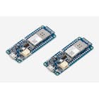
1. The mini Arduino pro microprocessor

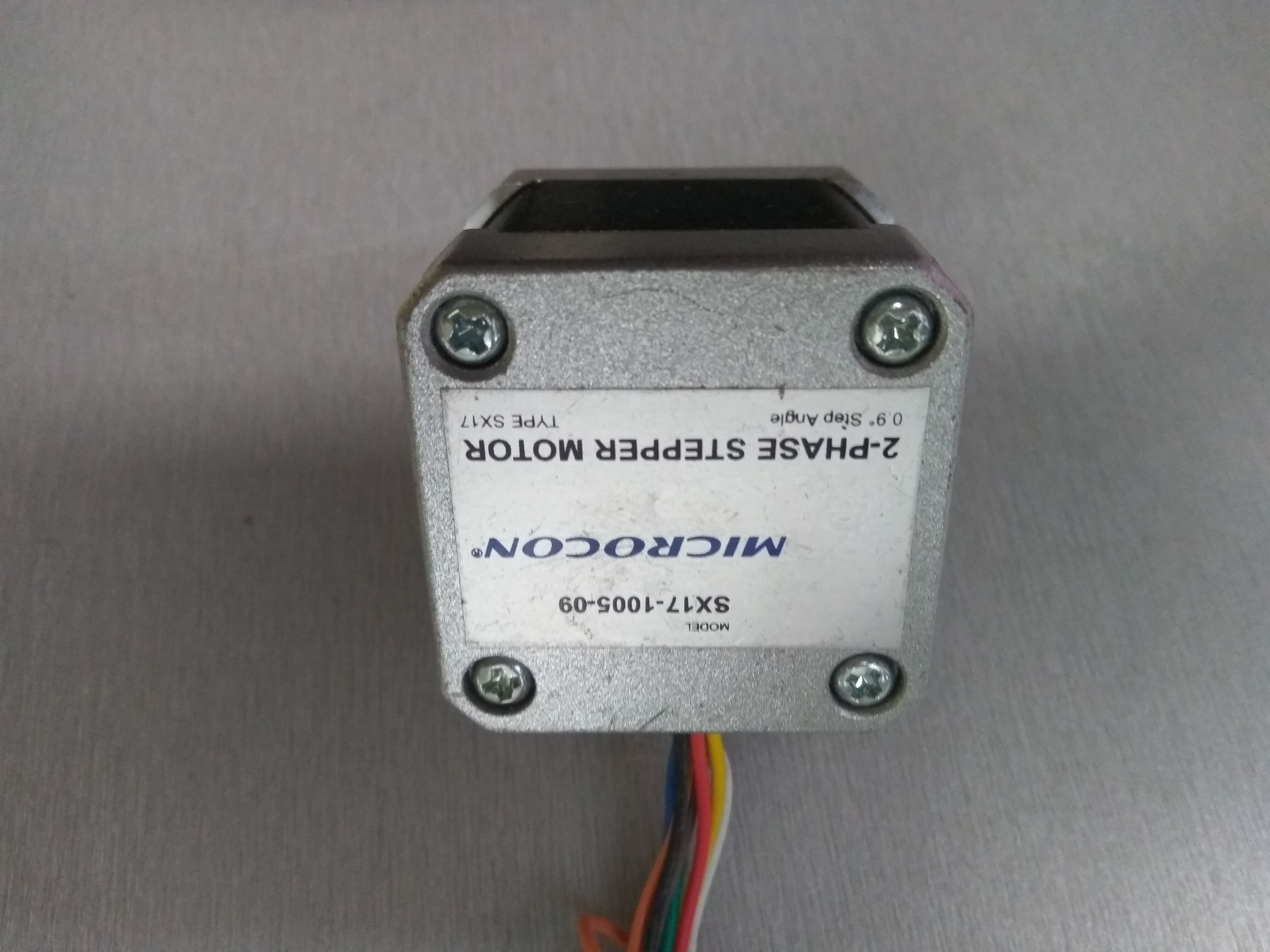
2. A 2-phased stepper motor of the Microcon (motor) which is set to rotate continuously 360 degrees and switches to on / off mode using a switch

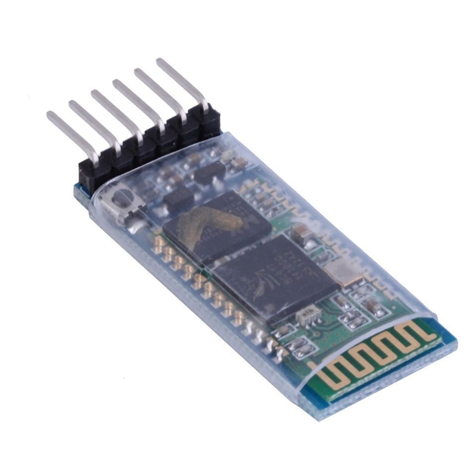
3. A Bluetooth shield for Arduino to achieve microprocessor communication with the computer to transport the code

4. On / off switch

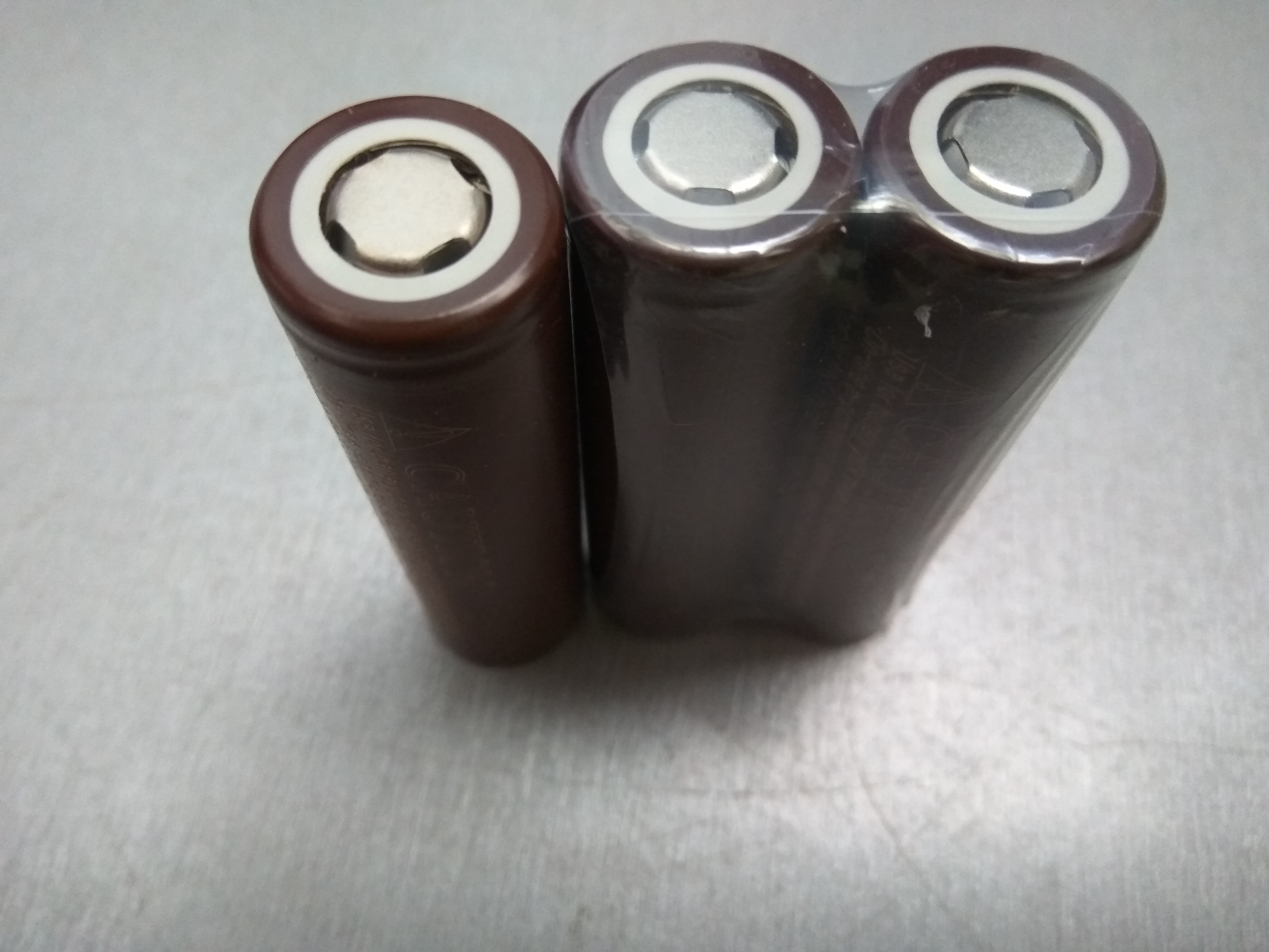
5. Three (3) Lion batteries (3000mAh each) rechargeable to supply power to the engine and microprocessor

6. The Processing 3 software for the visualization of the radar screen

7. The Arduino Software

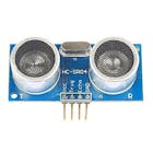
8. Two 2 ultrasonic distance sensors for Arduino

9. One (1) DRV8825 Stepper Motor Driver Carrier, High Circle

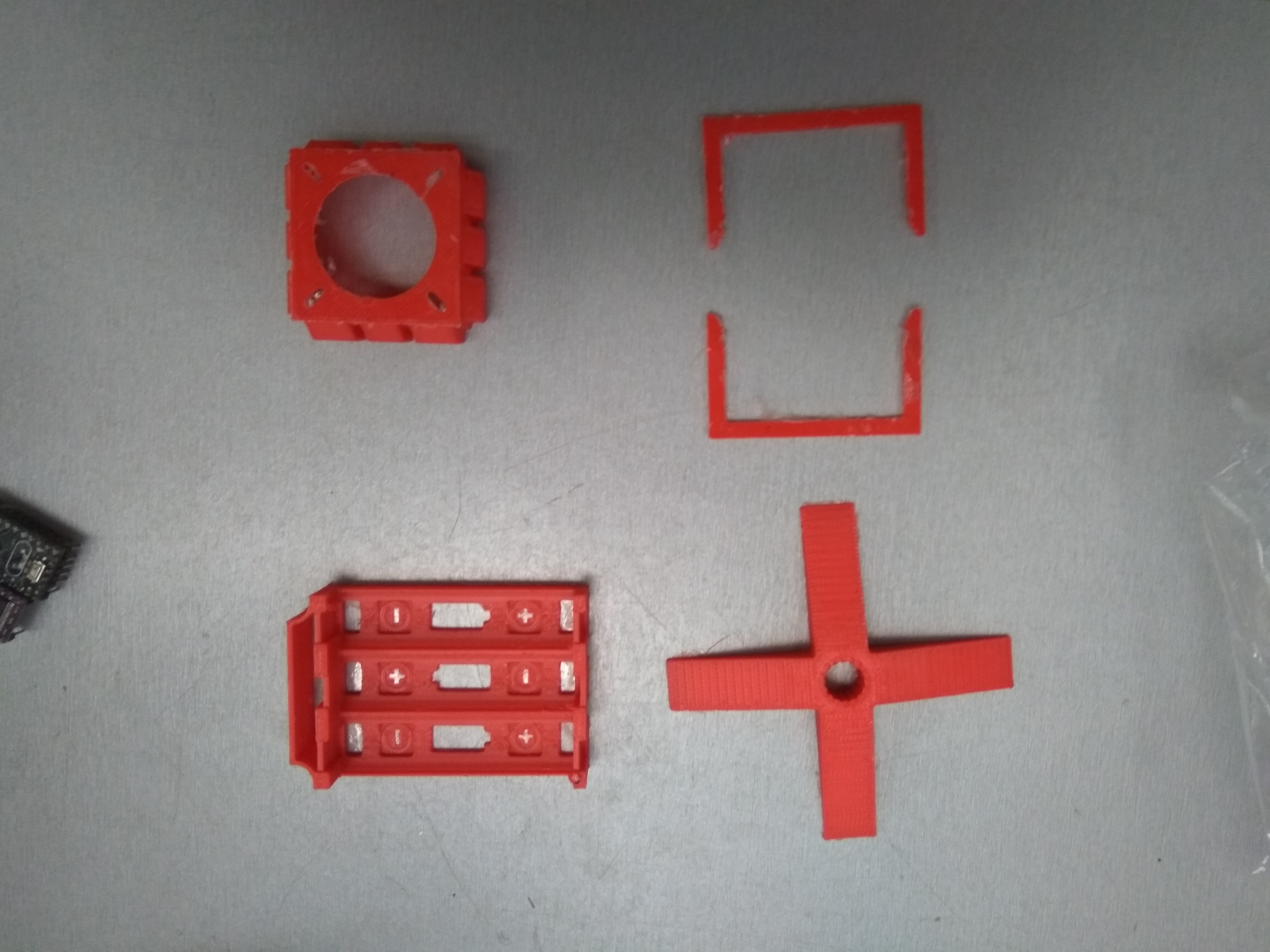
10. Stand base made by 3d printer

We thanks Petr Zverina for making for us the stand base with his 3D printer.

Description:

The whole MicroLab Radar codeProcessing
//this is the whole code running via Processing 3.3.6. (MicroLab-Greece)
//All parts tests carried out in Arduino IDE. The plastic parts are made via 3D printer
import processing.serial.*; //import library in order serial interface data
import java.awt.event.KeyEvent; //import library for reading data from serial port
import java.io.IOException;
Serial myPort;//defines serial object
//variable definition
String angle="";
String distance="";
String data="";
String noObject;
float pixsDistance;
int iAngle, iDistance;
int index1=0;
int index2=0;
PFont orcFont;

void setup() {
 
  size (860, 860); 

 smooth();
 myPort = new Serial(this,"COM5", 57600); //starting communication with specofic port
 myPort.bufferUntil('.'); //reads data from port delimited by '.'

}

void draw() {
 
 fill(98,245,31); 
 //simulation of moving line (motion and fade)
 noStroke();
 fill(0,4); 
 rect(0, 0, width, height); 
 fill(7,246,23);
//draws the radar calling functions
 drawRadar(); 
 drawLine();
 drawObject();
 drawText();
}

void serialEvent (Serial myPort) { //start reading data from specified port
 //reads data from port delimited by (.) and assigns them in string defined variable "data"
 data = myPort.readStringUntil('.');
 data = data.substring(0,data.length()-1);

 index1 = data.indexOf(","); //detect charachter ',' and assign it to the defined string variable 'index1'
 angle= data.substring(0, index1); // read the data from position "0" to position of the variable index1 or the value of the angle, via bluetooth, sents into the Serial Port
 distance= data.substring(index1+1, data.length()); //reads the data from index() from first to last (distance)
 //convert stings variables into integer
 iAngle = int(angle);
 iDistance = int(distance);
}

void drawRadar() {
 pushMatrix();
 translate(420,420); //moving the coordinats start
 noFill();
 strokeWeight(1);
 stroke(255,245,255);
 // draws the arc lines
  arc(0,0,860,860,0,TWO_PI);
 arc(0,0,720,720,0,TWO_PI);
 arc(0,0,580,580,0,TWO_PI);
 arc(0,0,440,440,0,TWO_PI);
 arc(0,0,300,300,0,TWO_PI);
 arc(0,0,160,160,0,TWO_PI);
 arc(0,0,20,20,0,TWO_PI);
//darw of angle lines
 line(-width/2.0,0,width/2.0,0);
 line(0,0,-width*cos(radians(30)),-width*sin(radians(30)));
 line(0,0,-width*cos(radians(60)),-width*sin(radians(60)));
 line(0,0,-width*cos(radians(90)),-width*sin(radians(90)));
 line(0,0,-width*cos(radians(120)),-width*sin(radians(120)));
 line(0,0,-width*cos(radians(150)),-width*sin(radians(150)));
 line(0,0,-width*cos(radians(180)),-width*sin(radians(180)));
 line(0,0,-width*cos(radians(210)),-width*sin(radians(210)));
 line(0,0,-width*cos(radians(240)),-width*sin(radians(240)));
 line(0,0,-width*cos(radians(270)),-width*sin(radians(270)));
 line(0,0,-width*cos(radians(300)),-width*sin(radians(300)));
 line(0,0,-width*cos(radians(330)),-width*sin(radians(330)));
 line(0,0,-width*cos(radians(360)),-width*sin(radians(360)));
 line(-width*cos(radians(30)),0,width/2.0,0);
 popMatrix();
}
 //this function draws the detected object converting the distance into pixels on screen according the angle
void drawObject() {
 pushMatrix();
 translate(420,420);
 strokeWeight(3);
 stroke(255,10,10); 
 pixsDistance = iDistance*2; //converting distance from cm into pixels
 //with (if) we define the limit range to 2meter  (200cm) ! anyone can change the limits according to sensors specifications and drwas the line converting distance into pixel
 if(iDistance<200){
   line(pixsDistance*cos(radians(iAngle)),-pixsDistance*sin(radians(iAngle)),950*cos(radians(iAngle)),-950*sin(radians(iAngle)));
  }
 popMatrix();
}
//this function draws the radar rotatable line
void drawLine() {
 pushMatrix();
 strokeWeight(6);
 stroke(10,74,250);
 translate(420,420); 
 line(0,0,950*cos(radians(iAngle)),-950*sin(radians(iAngle))); 
 popMatrix();
}
//function drawing text on screen nad its values taking from sensors
void drawText() {
 
 pushMatrix();
 
 fill(0,0,0);
 noStroke();
 rect(0, 1010, width, 600);
 textSize(15);
 fill(5,255,5);
 
 translate(640,294);
 rotate(-radians(-5));
 text("30°",0,0);
 resetMatrix();
 translate(548,200);
 rotate(-radians(-5));
 text("60°",0,0);
 resetMatrix();
 translate(420,160);
 rotate(radians(0));
 text("90°",0,0);
 resetMatrix();
 translate(292,199);
 rotate(radians(-30));
 text("120°",0,0);
 resetMatrix();
 translate(202,296);
 rotate(radians(-60));
 text("150°",0,0);
 resetMatrix();
 translate(166,422);
 rotate(radians(-90));
 text("180°",0,0);
 resetMatrix();
 translate(197,550);
 rotate(radians(-110));
 text("210°",0,0);
 resetMatrix();
 translate(292,641);
 rotate(radians(360));
 text("240°",0,0);
 resetMatrix();
 
 translate(420,677);
 rotate(radians(-360));
 text("270°",0,0);
 resetMatrix();
 
 translate(544,640);
 rotate(radians(-380));
 text("300°",0,0);
 resetMatrix();
 
 translate(641,547);
 rotate(radians(-5));
 text("330°",0,0);
 resetMatrix();
 
  translate(674,422);
 rotate(radians(-360));
 text("360°",0,0);
 resetMatrix();
 
 translate(50,50);
 rotate(radians(0));
 textSize(17);
 fill(255,103,1);
 text("MicroLab Radar",0,0);
 
 resetMatrix();
 
 if(iDistance>200) {
noObject = "Out of Range";
}
else {
noObject = "In Range";
}
fill(0,0,0);
noStroke();
rect(0, 1010, width, 1080);
fill(26,230,32);

textSize(20);
text("Object: " + noObject, 250, 50);
text("Angle: " + iAngle +" °", 500, 50);
text("Distance: ", 650, 50);
if(iDistance<200) {
text(" " + iDistance +" cm", 750, 50);
}
 
 popMatrix(); 


 }
Motor sketch (code)Arduino
Defines and regulates the 2-phased motor rotation
//This sketch defines and regulate the 2-phased stepper motor
int trigPinA =13;
int echoPinA=12;
volatile unsigned long durationA;
volatile int distanceA;
volatile uint16_t counter;


int trigPinB =11;
int echoPinB=10;
long durationB;
int distanceB;

volatile unsigned long Start;
unsigned long  timer1_counter;
void setup() {
  // put your setup code here, to run once:
  // Arduino initializations
Serial.begin(9600);

Serial.write("AT+NAMERADAR");

  delay(1000);

  Serial.write("AT+PIN1234");

  delay(1000);
 Serial.write("AT+BAUD8");


  delay(1000);

Serial.end();

  
  Serial.begin(115200);

 //pinMode(2,INPUT);
 pinMode(2, OUTPUT);

 pinMode(3,OUTPUT);
 pinMode(9,OUTPUT);
  pinMode(10,INPUT);
   pinMode(12,INPUT);
 pinMode(11,OUTPUT);
 pinMode(13,OUTPUT);
 digitalWrite(2,LOW);
 digitalWrite(9,LOW);
 digitalWrite(2,HIGH);
 //pinMode(2,OUTPUT);


  // initialize timer1 
  noInterrupts();           // disable all interrupts
  TCCR1A = 0;
  TCCR1B = 0;

  // Set timer1_counter to the correct value for our interrupt interval
  timer1_counter = 65505;   // preload timer 65536-16MHz/256/100Hz
  //timer1_counter = 64286;   // preload timer 65536-16MHz/256/50Hz
  //timer1_counter = 34286;   // preload timer 65536-16MHz/256/2Hz
  
  TCNT1 = timer1_counter;   // preload timer
  TCCR1B |= (1 << CS12);    // 256 prescaler 
  TIMSK1 |= (1 << TOIE1);   // enable timer overflow interrupt
  interrupts();             // enable all interrupts


}


ISR(TIMER1_OVF_vect)        // interrupt service routine 
{
  TCNT1 = timer1_counter;   // preload timer
  digitalWrite(3, digitalRead(3) ^ 1);
  counter++;
  if (counter>=12800*2)
  counter=0;
}

void loop() {


digitalWrite(trigPinA, LOW);
delayMicroseconds(2);
// Sets the trigPin on HIGH state for 10 micro seconds
digitalWrite(trigPinA, HIGH);
delayMicroseconds(10);

digitalWrite(trigPinA, LOW);
//Reads the echoPin, returns the sound wave travel time in microseconds
durationA= pulseIn(echoPinA, HIGH);
distanceA= durationA*0.029/2;
    noInterrupts();  
    int i=(counter/2)/35.5555;
    interrupts();
  Serial.print(i);
  Serial.print(",");
  Serial.print(distanceA,DEC);
  Serial.print(".");


digitalWrite(trigPinB, LOW);
delayMicroseconds(2);
// Sets the trigPin on HIGH state for 10 micro seconds
digitalWrite(trigPinB, HIGH);
delayMicroseconds(10);

digitalWrite(trigPinB, LOW);
//Reads the echoPin, returns the sound wave travel time in microseconds
durationB= pulseIn(echoPinB, HIGH);
distanceB= durationB*0.029/2;
    noInterrupts();  
     i=(180+(counter/2)/35.5555);
     if(i>360)
     i=i-360;
    interrupts();
  Serial.print(i);
  Serial.print(",");
  Serial.print(distanceB,DEC);
  Serial.print(".");


delay(0);


}

Description:

2-phased stepper motor of the Microcon
The motor has regulated for continiously rotation
Img 20180220 093442 wai0fkzvq4
Arduino mini pro
Img 20180220 093527 xfwtrdljd8
DRV8825 Stepper Motor Driver Carrier
Img 20180220 093537 zutj07gfwr
Plastics
All the plastic parts have made via 3D printer
Img 20180220 093759 cw0qf4bom7
Batteries Lion 3000mAh each
The batteries are rechargeable
Img 20180220 093653 2znu2udosz
ultrasonic distance sensors for Arduino
Radar uses two (2) ultrasonic sensors
Ultrasonic 9teef05bgl
HC-05 6 Pin Wireless Bluetooth RF Transceiver Module Serial For Arduino
Radar gets the data via bluetooth communication
Hc 05 tekhmguoqj


YOU MIGHT ALSO LIKE