Autopilot for Sailing Boats (Automatic Steering System) © GPL3+
DESCRIPTION
I love sailing alone because when a man is on the sea with his sailing boat he got everything he needs to evolve to a greater level. Sailing in raw sea with bad weather can be very hard but if he choose good weather days with sun and nice wind the enjoy will be at maximum.
Happiness means infinite horizons, perfect athletic technics, optimal choices, but also human things as a good coke and a tasty sandwich! Exactly in this time come in help Autopilot: it works instead of you meanwhile you have your 5:00pm tea & biscuits on the sea. :-)
What Autopilot can do for you:A sailing boat does not have an engine and cannot go along a programmed path from harbour to the beach, then to the fishing spot, turn around the Lighthouse and back, all itself, it cannot.
Whole work is done by the Sailor, we have to understand it at this point: trimming sails, take under control weather and the wind source/speed, harden or release ropes, mind other boats, decide direction and steering... When the Sailor decide for a break, let say just 10 seconds or up a few minutes (the famous "tea time"), he switches Autopilot on. In a cup of seconds its GPS acquire position, speed and direction of the boat and is able to mantain the direction (route). The steering system, a stick connected to the rudder, usually moved by the expert Sailor hands, now is under control by Autopilot through the Stepper Motor connected to it by pulleys and ropes.
Control the rudder is a continuous work of fine or gross tuning. Smaller (lighter) is the boat and greater will be the changes of direction factors influences it: sea waves, direction and pressure of the wind, shifting of the weight on board by Sailor movements, sea currents. But the Sailor is always awake, even with autopilot on, making changes to the actual route by the way of remote control: there are 4 buttons on it, labelled +1 -1 +10 -10, for small or big changes in degrees, increasing or decreasing the value. These buttons are present on the Autopilot too, the green (right) and the red (left) ones. The blue button (middle) is for activate or deactivate the Autopilot, the pause. It is also a black button for setting up parameters in memory.

The main processing is done by MPU Arduino Uno. The other MPU, Arduino Nano, is the watchdog: I know it does exist a kind of watchdog inside the Uno but I liked to do it with and independent external processor, it is a life long dream I covered, I am happy now! Uno has to feed Nano by the way of pin 3 -> A0 putting it high/low, 5/0 volts, at least one time every 2.5 seconds (feedingInterval); if not, it means the Uno is "sleeping" or "blocked", and Nano resets Uno... It never happened yet, can you believe?
It is used a popular display in conjunction with a i2c circuit converter both soldered together, finally using just 4 wires to significantly spare digital pins to communicate with Uno. Also the way to connect buttons and remote control to is done by resistance voltage dividers to reach the goal to use as less MPU's ports as possibile; I chosen 1% precision resistors, the analog comparing values should be between values I put into the code; in case of no recognition of some buttons because you choose other kind of resistors, just make some changes to constants too (modify code at "checkRfRC()" and "checkHWButtons()"). The RF 433Mhz Remote Control (RC) circuit works well; to improve distance coverage and chances to success, I added a coil antenna you could made by yourself with a piece of copper wire; I tested it 10 meters away but I think it can work even at 20 meters or more, more than enough considering the target sailing boat I used to testing Autopilot has been just a 4.20 meters long.
For the GPS unit I used at the beginning a good EM406A but unfortunately I discovered it suffered of Week-Rollover-Bug, it was too old, then I had to change it with an excellent and popular Beitian BN-220T. With its configuration software please set it to "spit" out 2 times per second (2Hz) just necessary "$GNRMC" NMEA serial sentence. The GPS sends (TX) serial data to pin 0 (RX) of Uno. The data contains all navigation data used to calculate correction to do by the Motor: date, time, position latitude and longitude, true course, speed and validity of satellites fix. Due to the fact Arduino's IDE programming uses pin 0 (RX) port too, remember to disconnect temporary the GPS during this operation...
Another dream of mine was to use an EEPROM. The IC 2404 is a beautiful 512 bytes i2c integrated circuit I used to read/write in this memory chip some parameters for Stepper Motor movements I will explain later under "Software" paragraph.
Components List:- Arduino Uno as MPU
- Arduino Nano as WatchDog
- Beitian BN-220T GPS
- Stepper Motor, model 23LM, 54 steps = 1/4 of revolution
- Controller Keyes L298 for motor
- RF433Mhz RC XD-YK04 + 4 buttons remote control + coil antenna
- 6 Buttons normal open (2xRed, 2xGreen, 1xBlack and 1xBlue)
- Switch for power on/off (White)
- Female + Male 6 pin round connectors for external Stepper Motor
- Buzzer
- Display LCD1602 2x16 characters + i2c converter circuit
- 3 LEDS (red, blue and yellow))
- IC 24c04 i2c eeprom
- IC 4051 multiplexer
- Battery LiPo 2s 7.4v 2600mA
- IC 7805 voltage regulator + heat dissipator
- Thermistor NTC MF52-103 10k
- Resettable Fuse 2A
- 6x 1N4148 diods (D1-D6)
- Resistors on Power shield (R1-R4=10k, R5=100k)
- Resistors on Autopilot shield (R1=330, R2=1k, R3=2k, R4=5.1k, R5=1k, R6/R7/R14=330, R8-R13=10k, R15=10M)
- Capacitors (C1=470uF 16v, C2=100n)
- 2W 0.22 Ohm resistor (R6)
- Male pins
- Female long-pins headers
- Case transparent and "waterproof"
There are a few sensors on the circuit all connected to Arduino Uno by the help of IC 4051 multiplexer. It is a Thermistor to take under control voltage regulator heating dissipator temperature, a 2W resistor and 4x10k as voltage dividers to calculate Ampere as power consumption of whole circuit. Also the battery voltage is taken under control: LiPo are known to be critical when single elements are discharged below 3.3v; this circuit has a two elements (2S) LiPo in one package, in case of low voltage (below 7.0v) the buzzer will inform you with short quick beeps. Do not wait too long to switch off, and recharge soon! The Leds: yellow one blinking at 1Hz let you know the WatchDog is working; the blue one is on when Autopilot is on, off if paused; the red led blinks when one of the remote control buttons is pressed.
All circuit works at 5.0v supplied by LiPo 2S 7.4v 2600mA/h battery and IC 7805 voltage regulator. Current should not be greater than 800mA, but usually it is around 100-450mA. Please put on it an heating dissipator. The Thermistor is placed on it and the buzzer will beep if temperature exceed 50°C.


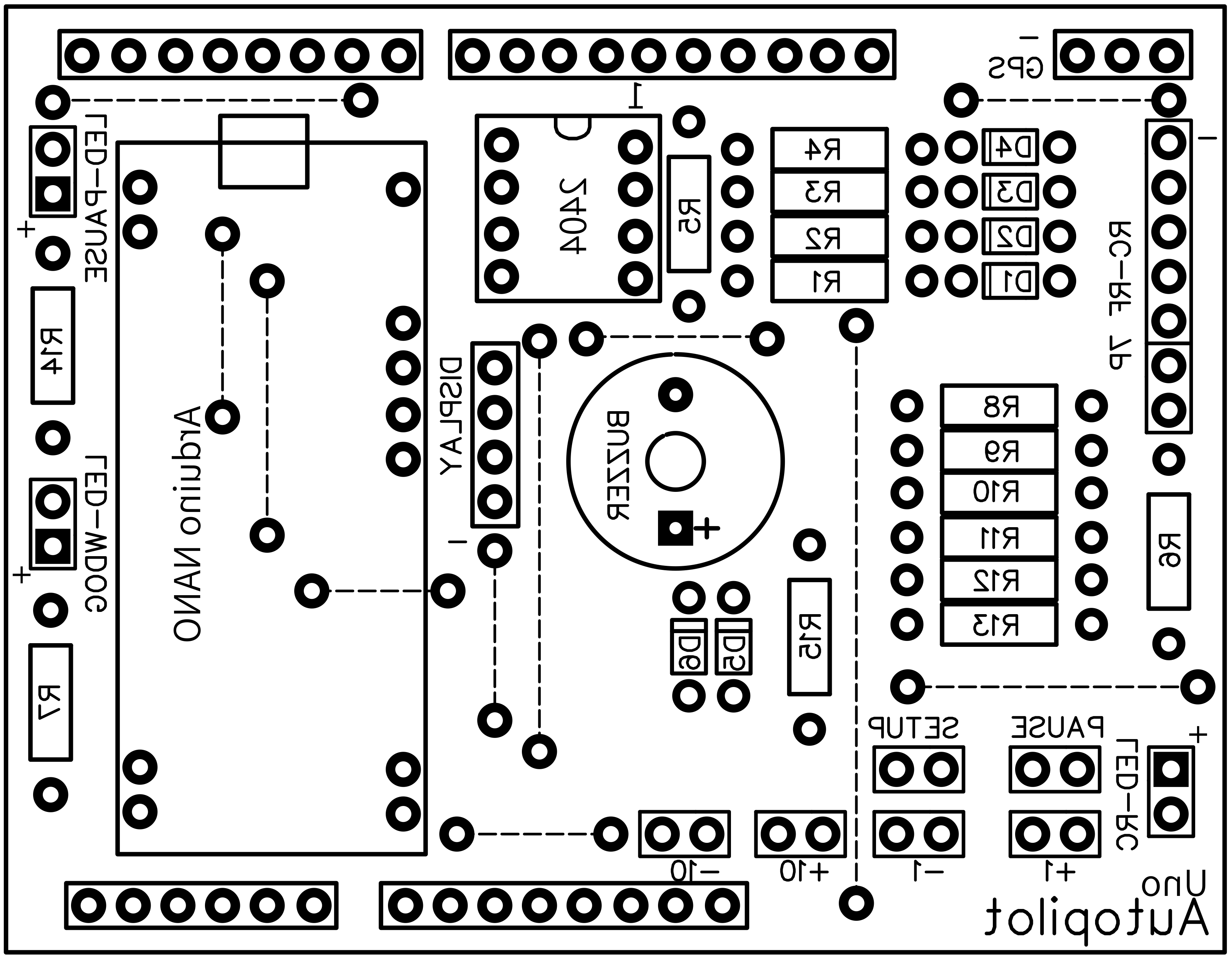
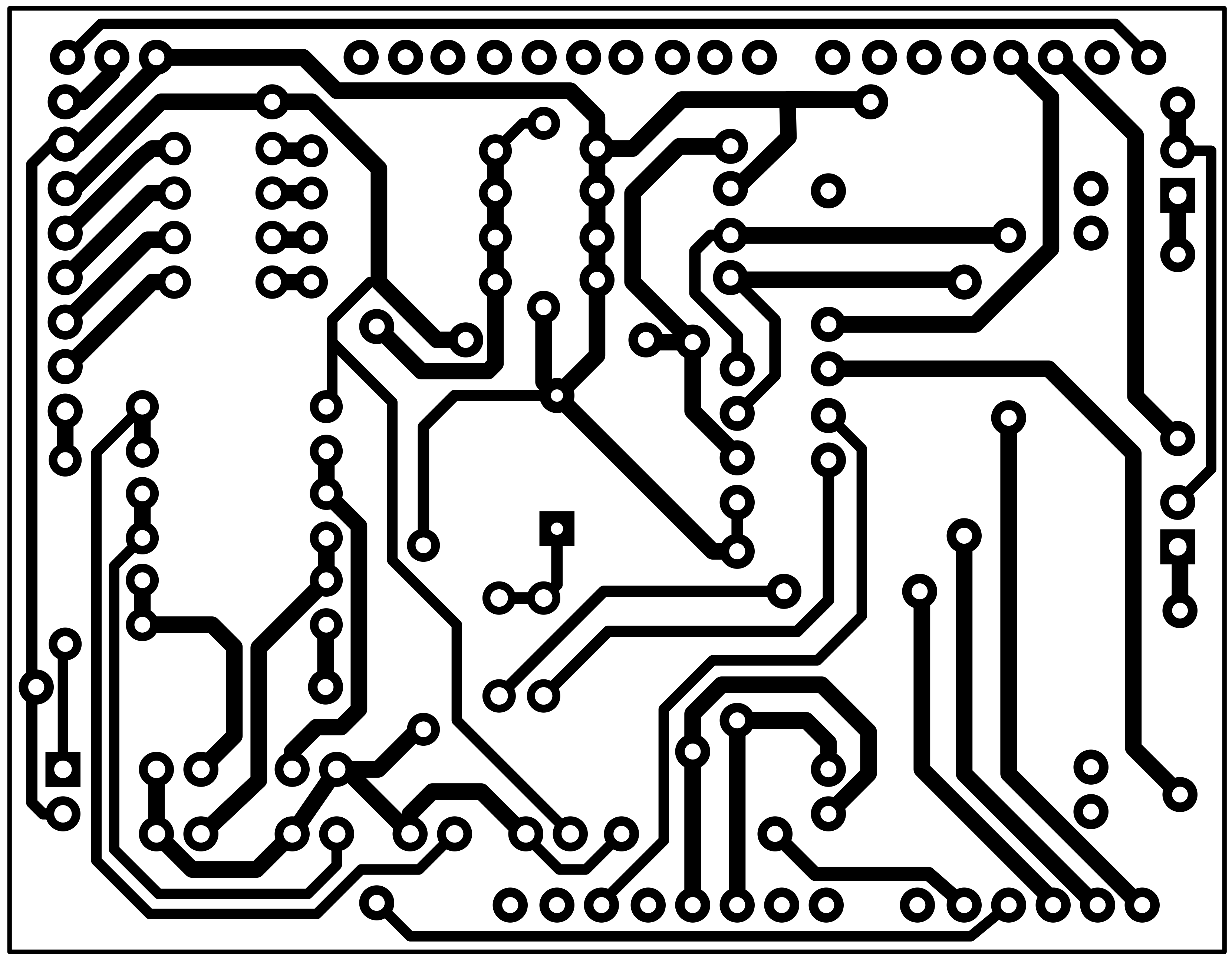
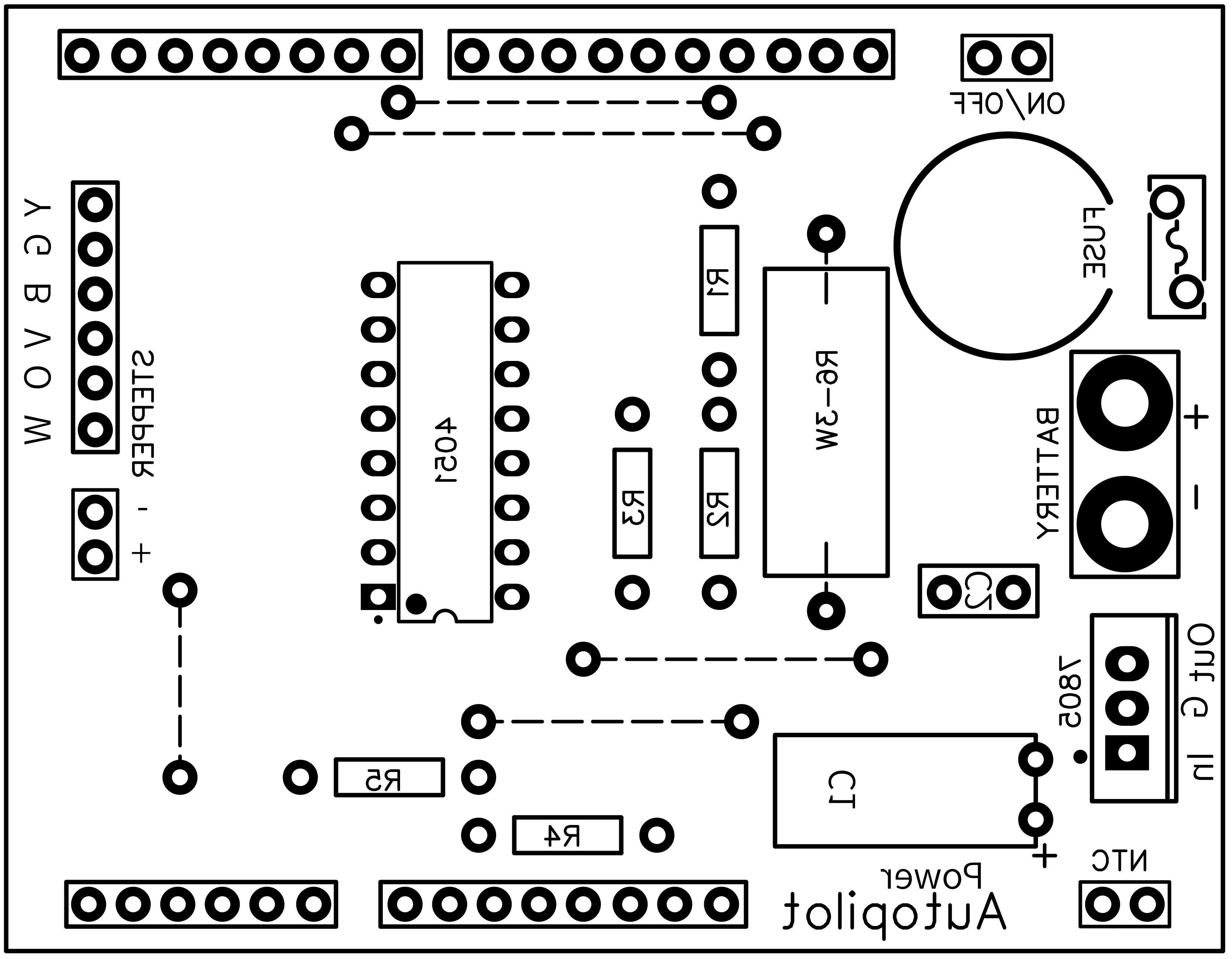
Is used single face PCBs for that reason I had to include a few wire jumpers (the dotted line ones) to solve routes for whole circuits. Is shown here the components faces but below you have all files, components and solder faces, mirrored, for downloading and printing by the way of a laser printer on "yellow" or "blue" sheets. I used the yellow ones but they say the blue are better (but the price is significantly higher). When printing remember to disable toner saving settings, use instead 1200 dpi resolution to have deep real black result. The toner transfer process from magic sheets to PCBs is made by the use of an hot iron... Printing on both faces, also on the components face, makes it easy to recognise positioning of items and even makes the project "professional".
Both PCBs are sized to fit one over the other Arduino Uno as a stack: first Power unit then Autopilot unit over all.
My choice has been to put all things together, PCBs, MPUs, RC, Motor Driver circuit, battery, GPS, buttons, switch, wires, connectors, etc. thinking to reuse them one day: I did not solder them together, I used headers and popular Dupont wires/connections instead. There are around 200 unsoldered connections then, it means unexpected and unwanted malfunctions or different behaviour of the circuit can happen from time to time, it is normal. Suggestion is to solder everything for a more stable circuit!


Pressing the black button on the side of the box it enters in Setup mode; this can be done also during active navigation, it is unnecessary to enter Pause first. The 1st page of the display shows battery voltage (V=7.83), power consumption (mA=177) and temperature of the thermistor sensor near dissipator (38°C); pressing again and again the black button you enter next pages; the 2nd, 3th, 4th and 5th page show the parameters listed below and you may change these values by the way of -1 and +1 buttons. The 6th page shows "Updating..." if you changed something, values are saved in the EEPROM memory.
- Interval: i.e. 2000 mSec, is the time between one try and another by Stepper Motor to restore "H" heading to the "R" route, moving the rudder stick right or left;
- Minimum: i.e. 2°, is the minimum amount of degrees out-of-route to have Autopilot intervention; up to this value the rudder stays at central position steady;
- Max: i.e. 40°, is the maximum steering change at a time by Stepper Motor; if calculation made is for 50° change, in reality Stepper will move only 40°;
- Coeffic.: i.e. 1.50 x °, is the coefficient for steering change at a time; if calculation made is for 40° change, in reality Stepper Motor will move for (40 x 1.50)=60°;
These parameters are necessary to fine tuning Autopilot when installed on the sailing boat. Responseness, sensitivity and smoothness depend by the diameter of the pulleys, how many pulleys, the diameter of main pulley on the Stepper Motor, the sensitivity of the rudder, how length is the rudder stick connected on it, and so on. Let install everything and let try and make experience on board. Of course choose a sunny beautiful day with light wind for all testing phase!
How it works "live":You are navigating on the sea, on the lake or just around the harbour. It is the Tea Time and your coke and your favourite sandwich are waiting in the pocket. Here we are: switch Autopilot on and let it take satellite GPS fix, you should now read on the display actual speed in knots, clock and heading direction i.e. H270° (R=route to follow, H=actual heading) in degrees (remember 180°=south, 270°=west, 360° or 0°=north and 90°=east). R and H values are the same when in Pause mode (STOP is shown). Connect now the steering rope, from Stepper Motor to the rudder stick, and press blue button to start Autopilot steering; at this point Autopilot holds R=route direction and it takes under control what happen with H=heading. Heading number changes for sure, slowly or fast depending of weather conditions we already talked about. Autopilot then try to restore to R=route direction making corrections i.e. -10°, +5°, etc. until H value equals R value. You may decide some changes on Route and you can modify the number using red and green buttons on the unit (-1 -10 +1 +10) or by the way of remote control. To take back control of the steering you just have to press Pause blue button, disconnect the rope from the rudder stick continuing the job by your hands. Well done.

Software side:
The code is quite long but I hope it is clear enough to be easy understandable. In any case I would explain how it is doing. The sketch uses around 65% of program and around 45% of memory. Even using String class, mostly for Serial NMEA sentences manipulation, the whole elaboration flow is stable and solid; it uses "serialEvent()" to receive data from GPS two times per second, than calls "nmeaExtractData()" and finally it checks data packet with "nmea0183_checksum() to be sure of data integrity. If you use another make and model GPS be sure the sentences have the same structure or you have to make some changes here. For example EM406A uses "$GPRMC" packet id, BT220 uses "$GNRMC" instead... just a small name change... A useful link can help you with checksum test: https://nmeachecksum.eqth.net - Here an example of a complete NMEA sentence, it contains: id, time, validity, latitude, longitude, speed, true course, date, variation and checksum.
$GPRMC, 095836.000, A, 4551.9676, N, 01328.7118, E, 2.09, 341.84, 280519,, *08
During "Setup()" the EEPROM is checked: if new or unknown it is initialised (formatted). Parameters in memory are read/write as bytes: 0=0x29, 1=0x00, 2-3=interval, 4-5=min, 6-7=max, 8-11=coefficient (byte, byte, int, int, float). I handled with care EEPROM r/w operations, maybe too much defensive... Sensors are checked every 10 seconds through "readMuxSensors()" by multiplexer and can cause alarm if battery is low or temperature is high. The resolution of power consumption is low, steps of around 40mA. Hardware and RC buttons are checked continuously; what they do depends of the "IsSetup" boolean value as well as the display "RefreshDisplay()" does. The core of the code is the STEERING CONTROL section that calls "gomotor()" function to move the Stepper out and back; yes, it may moves the rudder 10° to the right and after interval value it moves back to zero rudder position, and so on after a new calculation round. As already said, steering work is made also during Setup because it affects just a few buttons and display behaviour. Whatchdog feeding is very simple but important: just puts on/off its Pin as soon as it can.
How to install on a Sailing Boat:
As it is shown in the picture below I chosen to place Autopilot and the Stepper Motor on the stern, both well fixed with bolts, etc.; a rope of 6mm diameter starts from main Motor pulley and go around two other pulleys placed on both sides. These two pulleys should be "hold" by two rings of bungee to keep slightly in tension the rope. At this point, finally, you have to decide how to connect the rope to the rudder stick; it has to be connected while you want Autopilot is in action, easy to connect and easy to disconnect. Keep Autopilot system away from water! :-)

News & Updates:
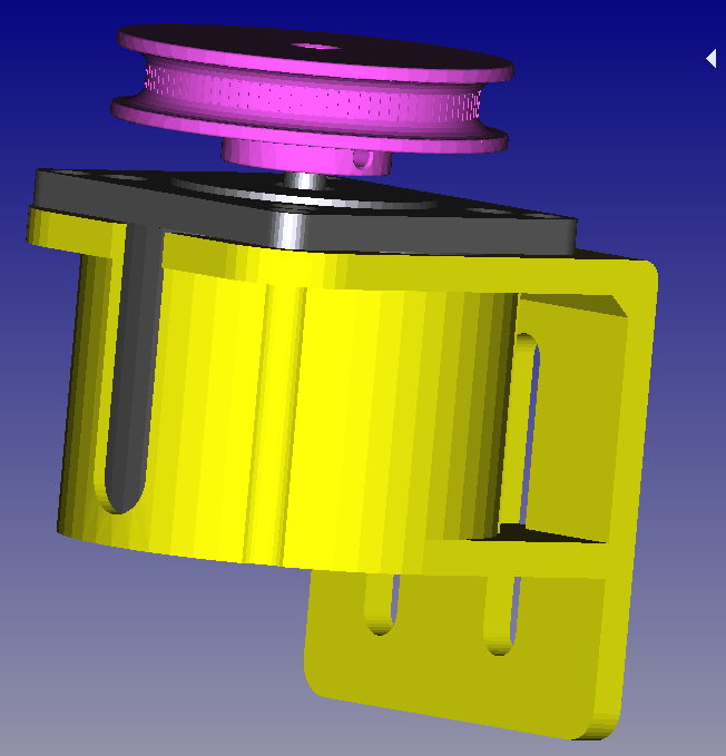
- 10.05.2020, added for downloading .STEP 3D CAD project files for stepper pulley (by me) and mounting plate (by Andrew Barney), and a 3D preview picture of them.
DISCLAIMER & WARNINGS:
Lets say this is a game we are playing here, nothing to take serious! A few years ago I went for a long trip, 16 months, around the World on a sailing boat. We extensively navigated with a real autopilot in all weather conditions, even bad weather conditions. A real autopilot is something very strong both hardware and software you have to trust to a lot. This Arduino Autopilot is a fantastic game to play with and to spend time for fun.
Have fun!
Marco Zonca

I love sailing alone because when a man is on the sea with his sailing boat he got everything he needs to evolve to a greater level. Sailing in raw sea with bad weather can be very hard but if he choose good weather days with sun and nice wind the enjoy will be at maximum.
Happiness means infinite horizons, perfect athletic technics, optimal choices, but also human things as a good coke and a tasty sandwich! Exactly in this time come in help Autopilot: it works instead of you meanwhile you have your 5:00pm tea & biscuits on the sea. :-)
What Autopilot can do for you:A sailing boat does not have an engine and cannot go along a programmed path from harbour to the beach, then to the fishing spot, turn around the Lighthouse and back, all itself, it cannot.
Whole work is done by the Sailor, we have to understand it at this point: trimming sails, take under control weather and the wind source/speed, harden or release ropes, mind other boats, decide direction and steering... When the Sailor decide for a break, let say just 10 seconds or up a few minutes (the famous "tea time"), he switches Autopilot on. In a cup of seconds its GPS acquire position, speed and direction of the boat and is able to mantain the direction (route). The steering system, a stick connected to the rudder, usually moved by the expert Sailor hands, now is under control by Autopilot through the Stepper Motor connected to it by pulleys and ropes.
Control the rudder is a continuous work of fine or gross tuning. Smaller (lighter) is the boat and greater will be the changes of direction factors influences it: sea waves, direction and pressure of the wind, shifting of the weight on board by Sailor movements, sea currents. But the Sailor is always awake, even with autopilot on, making changes to the actual route by the way of remote control: there are 4 buttons on it, labelled +1 -1 +10 -10, for small or big changes in degrees, increasing or decreasing the value. These buttons are present on the Autopilot too, the green (right) and the red (left) ones. The blue button (middle) is for activate or deactivate the Autopilot, the pause. It is also a black button for setting up parameters in memory.
The main processing is done by MPU Arduino Uno. The other MPU, Arduino Nano, is the watchdog: I know it does exist a kind of watchdog inside the Uno but I liked to do it with and independent external processor, it is a life long dream I covered, I am happy now! Uno has to feed Nano by the way of pin 3 -> A0 putting it high/low, 5/0 volts, at least one time every 2.5 seconds (feedingInterval); if not, it means the Uno is "sleeping" or "blocked", and Nano resets Uno... It never happened yet, can you believe?
It is used a popular display in conjunction with a i2c circuit converter both soldered together, finally using just 4 wires to significantly spare digital pins to communicate with Uno. Also the way to connect buttons and remote control to is done by resistance voltage dividers to reach the goal to use as less MPU's ports as possibile; I chosen 1% precision resistors, the analog comparing values should be between values I put into the code; in case of no recognition of some buttons because you choose other kind of resistors, just make some changes to constants too (modify code at "checkRfRC()" and "checkHWButtons()"). The RF 433Mhz Remote Control (RC) circuit works well; to improve distance coverage and chances to success, I added a coil antenna you could made by yourself with a piece of copper wire; I tested it 10 meters away but I think it can work even at 20 meters or more, more than enough considering the target sailing boat I used to testing Autopilot has been just a 4.20 meters long.
For the GPS unit I used at the beginning a good EM406A but unfortunately I discovered it suffered of Week-Rollover-Bug, it was too old, then I had to change it with an excellent and popular Beitian BN-220T. With its configuration software please set it to "spit" out 2 times per second (2Hz) just necessary "$GNRMC" NMEA serial sentence. The GPS sends (TX) serial data to pin 0 (RX) of Uno. The data contains all navigation data used to calculate correction to do by the Motor: date, time, position latitude and longitude, true course, speed and validity of satellites fix. Due to the fact Arduino's IDE programming uses pin 0 (RX) port too, remember to disconnect temporary the GPS during this operation...
Another dream of mine was to use an EEPROM. The IC 2404 is a beautiful 512 bytes i2c integrated circuit I used to read/write in this memory chip some parameters for Stepper Motor movements I will explain later under "Software" paragraph.
Components List:- Arduino Uno as MPU
- Arduino Nano as WatchDog
- Beitian BN-220T GPS
- Stepper Motor, model 23LM, 54 steps = 1/4 of revolution
- Controller Keyes L298 for motor
- RF433Mhz RC XD-YK04 + 4 buttons remote control + coil antenna
- 6 Buttons normal open (2xRed, 2xGreen, 1xBlack and 1xBlue)
- Switch for power on/off (White)
- Female + Male 6 pin round connectors for external Stepper Motor
- Buzzer
- Display LCD1602 2x16 characters + i2c converter circuit
- 3 LEDS (red, blue and yellow))
- IC 24c04 i2c eeprom
- IC 4051 multiplexer
- Battery LiPo 2s 7.4v 2600mA
- IC 7805 voltage regulator + heat dissipator
- Thermistor NTC MF52-103 10k
- Resettable Fuse 2A
- 6x 1N4148 diods (D1-D6)
- Resistors on Power shield (R1-R4=10k, R5=100k)
- Resistors on Autopilot shield (R1=330, R2=1k, R3=2k, R4=5.1k, R5=1k, R6/R7/R14=330, R8-R13=10k, R15=10M)
- Capacitors (C1=470uF 16v, C2=100n)
- 2W 0.22 Ohm resistor (R6)
- Male pins
- Female long-pins headers
- Case transparent and "waterproof"
There are a few sensors on the circuit all connected to Arduino Uno by the help of IC 4051 multiplexer. It is a Thermistor to take under control voltage regulator heating dissipator temperature, a 2W resistor and 4x10k as voltage dividers to calculate Ampere as power consumption of whole circuit. Also the battery voltage is taken under control: LiPo are known to be critical when single elements are discharged below 3.3v; this circuit has a two elements (2S) LiPo in one package, in case of low voltage (below 7.0v) the buzzer will inform you with short quick beeps. Do not wait too long to switch off, and recharge soon! The Leds: yellow one blinking at 1Hz let you know the WatchDog is working; the blue one is on when Autopilot is on, off if paused; the red led blinks when one of the remote control buttons is pressed.
All circuit works at 5.0v supplied by LiPo 2S 7.4v 2600mA/h battery and IC 7805 voltage regulator. Current should not be greater than 800mA, but usually it is around 100-450mA. Please put on it an heating dissipator. The Thermistor is placed on it and the buzzer will beep if temperature exceed 50°C.
Is used single face PCBs for that reason I had to include a few wire jumpers (the dotted line ones) to solve routes for whole circuits. Is shown here the components faces but below you have all files, components and solder faces, mirrored, for downloading and printing by the way of a laser printer on "yellow" or "blue" sheets. I used the yellow ones but they say the blue are better (but the price is significantly higher). When printing remember to disable toner saving settings, use instead 1200 dpi resolution to have deep real black result. The toner transfer process from magic sheets to PCBs is made by the use of an hot iron... Printing on both faces, also on the components face, makes it easy to recognise positioning of items and even makes the project "professional".
Both PCBs are sized to fit one over the other Arduino Uno as a stack: first Power unit then Autopilot unit over all.
My choice has been to put all things together, PCBs, MPUs, RC, Motor Driver circuit, battery, GPS, buttons, switch, wires, connectors, etc. thinking to reuse them one day: I did not solder them together, I used headers and popular Dupont wires/connections instead. There are around 200 unsoldered connections then, it means unexpected and unwanted malfunctions or different behaviour of the circuit can happen from time to time, it is normal. Suggestion is to solder everything for a more stable circuit!
Pressing the black button on the side of the box it enters in Setup mode; this can be done also during active navigation, it is unnecessary to enter Pause first. The 1st page of the display shows battery voltage (V=7.83), power consumption (mA=177) and temperature of the thermistor sensor near dissipator (38°C); pressing again and again the black button you enter next pages; the 2nd, 3th, 4th and 5th page show the parameters listed below and you may change these values by the way of -1 and +1 buttons. The 6th page shows "Updating..." if you changed something, values are saved in the EEPROM memory.
- Interval: i.e. 2000 mSec, is the time between one try and another by Stepper Motor to restore "H" heading to the "R" route, moving the rudder stick right or left;
- Minimum: i.e. 2°, is the minimum amount of degrees out-of-route to have Autopilot intervention; up to this value the rudder stays at central position steady;
- Max: i.e. 40°, is the maximum steering change at a time by Stepper Motor; if calculation made is for 50° change, in reality Stepper will move only 40°;
- Coeffic.: i.e. 1.50 x °, is the coefficient for steering change at a time; if calculation made is for 40° change, in reality Stepper Motor will move for (40 x 1.50)=60°;
These parameters are necessary to fine tuning Autopilot when installed on the sailing boat. Responseness, sensitivity and smoothness depend by the diameter of the pulleys, how many pulleys, the diameter of main pulley on the Stepper Motor, the sensitivity of the rudder, how length is the rudder stick connected on it, and so on. Let install everything and let try and make experience on board. Of course choose a sunny beautiful day with light wind for all testing phase!
How it works "live":You are navigating on the sea, on the lake or just around the harbour. It is the Tea Time and your coke and your favourite sandwich are waiting in the pocket. Here we are: switch Autopilot on and let it take satellite GPS fix, you should now read on the display actual speed in knots, clock and heading direction i.e. H270° (R=route to follow, H=actual heading) in degrees (remember 180°=south, 270°=west, 360° or 0°=north and 90°=east). R and H values are the same when in Pause mode (STOP is shown). Connect now the steering rope, from Stepper Motor to the rudder stick, and press blue button to start Autopilot steering; at this point Autopilot holds R=route direction and it takes under control what happen with H=heading. Heading number changes for sure, slowly or fast depending of weather conditions we already talked about. Autopilot then try to restore to R=route direction making corrections i.e. -10°, +5°, etc. until H value equals R value. You may decide some changes on Route and you can modify the number using red and green buttons on the unit (-1 -10 +1 +10) or by the way of remote control. To take back control of the steering you just have to press Pause blue button, disconnect the rope from the rudder stick continuing the job by your hands. Well done.
Software side:
The code is quite long but I hope it is clear enough to be easy understandable. In any case I would explain how it is doing. The sketch uses around 65% of program and around 45% of memory. Even using String class, mostly for Serial NMEA sentences manipulation, the whole elaboration flow is stable and solid; it uses "serialEvent()" to receive data from GPS two times per second, than calls "nmeaExtractData()" and finally it checks data packet with "nmea0183_checksum() to be sure of data integrity. If you use another make and model GPS be sure the sentences have the same structure or you have to make some changes here. For example EM406A uses "$GPRMC" packet id, BT220 uses "$GNRMC" instead... just a small name change... A useful link can help you with checksum test: https://nmeachecksum.eqth.net - Here an example of a complete NMEA sentence, it contains: id, time, validity, latitude, longitude, speed, true course, date, variation and checksum.
$GPRMC, 095836.000, A, 4551.9676, N, 01328.7118, E, 2.09, 341.84, 280519,, *08
During "Setup()" the EEPROM is checked: if new or unknown it is initialised (formatted). Parameters in memory are read/write as bytes: 0=0x29, 1=0x00, 2-3=interval, 4-5=min, 6-7=max, 8-11=coefficient (byte, byte, int, int, float). I handled with care EEPROM r/w operations, maybe too much defensive... Sensors are checked every 10 seconds through "readMuxSensors()" by multiplexer and can cause alarm if battery is low or temperature is high. The resolution of power consumption is low, steps of around 40mA. Hardware and RC buttons are checked continuously; what they do depends of the "IsSetup" boolean value as well as the display "RefreshDisplay()" does. The core of the code is the STEERING CONTROL section that calls "gomotor()" function to move the Stepper out and back; yes, it may moves the rudder 10° to the right and after interval value it moves back to zero rudder position, and so on after a new calculation round. As already said, steering work is made also during Setup because it affects just a few buttons and display behaviour. Whatchdog feeding is very simple but important: just puts on/off its Pin as soon as it can.
How to install on a Sailing Boat:
As it is shown in the picture below I chosen to place Autopilot and the Stepper Motor on the stern, both well fixed with bolts, etc.; a rope of 6mm diameter starts from main Motor pulley and go around two other pulleys placed on both sides. These two pulleys should be "hold" by two rings of bungee to keep slightly in tension the rope. At this point, finally, you have to decide how to connect the rope to the rudder stick; it has to be connected while you want Autopilot is in action, easy to connect and easy to disconnect. Keep Autopilot system away from water! :-)
News & Updates:
- 10.05.2020, added for downloading .STEP 3D CAD project files for stepper pulley (by me) and mounting plate (by Andrew Barney), and a 3D preview picture of them.
DISCLAIMER & WARNINGS:
Lets say this is a game we are playing here, nothing to take serious! A few years ago I went for a long trip, 16 months, around the World on a sailing boat. We extensively navigated with a real autopilot in all weather conditions, even bad weather conditions. A real autopilot is something very strong both hardware and software you have to trust to a lot. This Arduino Autopilot is a fantastic game to play with and to spend time for fun.
Have fun!
Marco Zonca