CAN Bus Using Arduino © GPL3+
DESCRIPTION
CAN Bus
CAN Bus, stand for Controller Area Network, is one type of serial communication that usually used in industrial and automotive environments. The real example of CAN Bus application can be found in speed car data sensor that can be transferred to the rpm indicator.
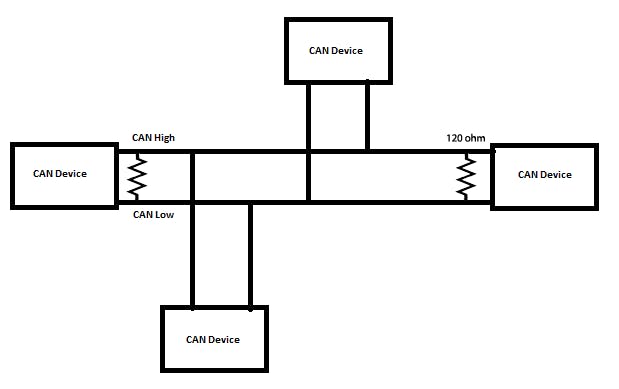
CAN Bus is a message based protocol that can be used for multiple device communication. The figure below represents that when several CAN devices are connected together like a network, each device can communicate with other devices in the node. In general, CAN communication range is in range 50Kbps to 1Mbps, with the distance range is 40 meters (at 1 Mbps) to 1000 meters (at 50 kbps).
In this communication, data is transferred in a certain message format. Each message consists of many segments, but there are two main segments: Identifier and Data. Identifier or CAN ID, or known as Parameter Group Number (PGN) is used to identify the CAN device in the CAN network, usually in 11 (Standard CAN) or 29 bit (Extended CAN) length, based on the CAN protocol. While Data is the message content to be sent, usually in 0 to 8 bytes length.
CAN Protocol consists of two wires : CAN_H and CAN_L to send and receive the message. This two wires act as a differential line where CAN signal is represented with the potential difference between them. If the difference is positive and larger than a certain minimum voltage, then the signal is 1, and if the difference between them is negative, it will be 0.
Usually, in CAN communication, twisted pair cable is used. And at the ends of the CAN networks, a single 120-ohm resistor is used. It is because the line should be balanced and tied to the same potential.
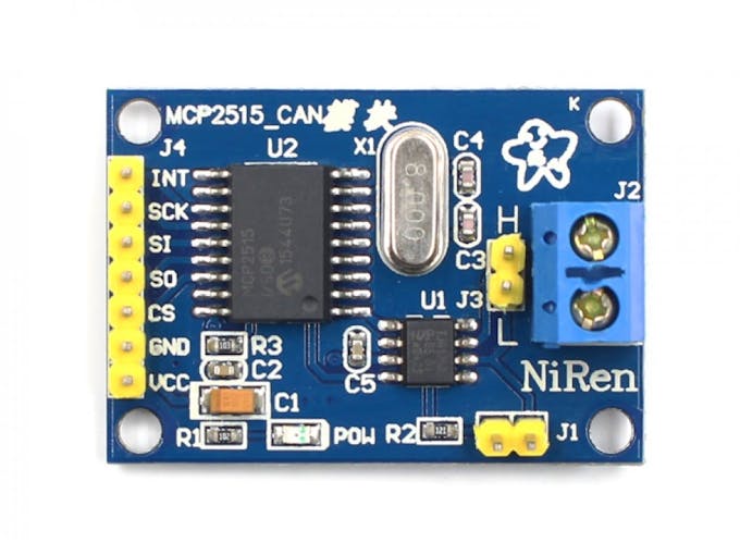
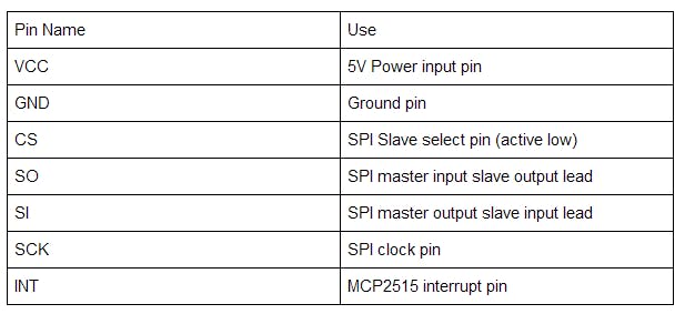
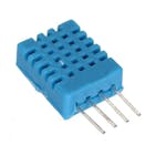
In this project, we are going to implement CAN Bus communication with MCP2515 module to communicate between two Arduino for sending temperature data from DHT11 sensor. This module uses 5V as operating voltage and has pinout configuration as shown in the following table.
The result is as shown below:
https://www.allaboutcircuits.com/technical-articles/introduction-to-can-controller-area-network/


CAN Bus
CAN Bus, stand for Controller Area Network, is one type of serial communication that usually used in industrial and automotive environments. The real example of CAN Bus application can be found in speed car data sensor that can be transferred to the rpm indicator.
CAN Bus is a message based protocol that can be used for multiple device communication. The figure below represents that when several CAN devices are connected together like a network, each device can communicate with other devices in the node. In general, CAN communication range is in range 50Kbps to 1Mbps, with the distance range is 40 meters (at 1 Mbps) to 1000 meters (at 50 kbps).
In this communication, data is transferred in a certain message format. Each message consists of many segments, but there are two main segments: Identifier and Data. Identifier or CAN ID, or known as Parameter Group Number (PGN) is used to identify the CAN device in the CAN network, usually in 11 (Standard CAN) or 29 bit (Extended CAN) length, based on the CAN protocol. While Data is the message content to be sent, usually in 0 to 8 bytes length.
CAN Protocol consists of two wires : CAN_H and CAN_L to send and receive the message. This two wires act as a differential line where CAN signal is represented with the potential difference between them. If the difference is positive and larger than a certain minimum voltage, then the signal is 1, and if the difference between them is negative, it will be 0.
Usually, in CAN communication, twisted pair cable is used. And at the ends of the CAN networks, a single 120-ohm resistor is used. It is because the line should be balanced and tied to the same potential.
In this project, we are going to implement CAN Bus communication with MCP2515 module to communicate between two Arduino for sending temperature data from DHT11 sensor. This module uses 5V as operating voltage and has pinout configuration as shown in the following table.
The result is as shown below:
https://www.allaboutcircuits.com/technical-articles/introduction-to-can-controller-area-network/
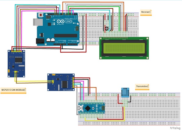
MCP2515 Module / DHT Sensor -> Arduino Nano
MPC2515 – VCC -> +5V
MPC2515 – GND -> GND
MPC2515 – CS -> D10 (SPI_SS)
MPC2515 – SO -> D12 (SPI_MISO)
MPC2515 - S I -> D11 (SPI_MOSI)
MPC2515 – SCK -> D13 (SPI_SCK)
MPC2515 – INT -> D2
DHT11 – VCC -> +5V
DHT11 – GND -> GND
DHT11 – OUT -> A0
For Receiver (Arduino 2)
MCP2515 Module -> Arduino Uno
VCC -> +5V
GND -> GND
CS -> 10 (SPI_SS)
SO -> 12 (SPI_MISO)
SI -> 11 (SPI_MOSI)
SCK -> 13 (SPI_SCK)
INT -> 2
Between two MCP2515
MCP2515 on Arduino Nano (Arduino 1) -> MCP2515 on Arduino Nano (Arduino 2)
H -> H
L -> L