Connecting Multiple Sensors to One Arduino Uno Serial Port © CC BY-NC
DESCRIPTION
In this tutorial, we will be expanding a single Arduino Uno UART (Rx/Tx) serial port so that multiple Atlas sensors can be connected. The expansion is done using 8:1 Serial Port Expander board. The Arduino's port is linked to the expander after which the signal is routed to the eight ports where the peripheral devices are connected. For simplicity purposes, we will be utilizing three ports, but with a few more steps, you can make the expansion to use all eight.
Communication is done via UART mode, and the results are displayed on the Arduino serial monitor. By default, the readings of the connected sensors are polled continuously. Individual channels can then be opened, which will allow the user to communicate with a specific sensor.
Advantages
- Expand a single UART (Rx/Tx) serial port into eight additional ports.
- Easily keep tabs on which channel is opened through the onboard LEDs on the Expander module.
- Works with the following Atlas EZO sensors: pH, salinity, dissolved oxygen (DO), temperature, oxidation-reduction potential (ORP), carbon dioxide (CO2), peristaltic pump.
- Real-time sensor output and user interaction.
Step 1: Assemble Hardware
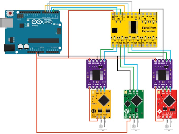
Assemble the hardware as shown in the schematic above.
Ensure that the sensors are in UART mode before connecting them to the Expander. For information on how to change between protocols refer to the following LINK.
The sensitivity of the sensors is what gives them their high accuracy. But this also means that they are subjected to interference from other electronics and as such electrical isolation is needed. Voltage isolators are used to isolate the dissolved oxygen and pH sensors from the salinity sensor. Without the isolators, readings are erratic. For more information on isolation refer to the following LINK.
Datasheets: 8:1 Serial Port Expander, EZO DO, EZO EC, EZO pH, Voltage Isolator
Step 2: Load Program Onto Arduino
The code for this tutorial makes use of a customized library and header file for the EZO circuits in UART mode. You will have to add them to your Arduino IDE to use the code. The steps below include the process of making the addition to the IDE.
a) Download Ezo_uart_lib, a zip folder from GitHub onto your computer.
b) On your computer, open the Arduino IDE (you can download the IDE from HERE if you do not have it).
c) In the IDE, go to Sketch -> Include Library -> Add.ZIP Library -> Select the Ezo_uart_lib folder you just downloaded. The appropriate files are now included.
d) Copy the code from Serial_port_expander_example onto your IDE work panel. You can also access it from the Ezo_uart_lib folder downloaded above.
e) Compile and upload the Serial_port_expander_example code to your Arduino Uno.
f) The serial monitor is used as the conduit of communication. To open the serial monitor, go to Tools -> Serial Monitor or press Ctrl+Shift+M on the keyboard. Set the baud rate to 9600 and select "Carriage return." The readings of the sensor should now be constantly displaying, and the user will be able to interact with individual sensors.
Demonstration
To open a channel denoted by P1- P8 on the Expander board, send the channel number followed by a colon and the command (if any). End the string with a carriage return (ENTER key on the keyboard). For example, 3:i will open channel three and request the device information.
To open a channel and not send a command just input the channel number followed by a colon. End the string with a carriage return (ENTER key on the keyboard). For example, 2: will open channel two. You can now send any commands specific to that sensor such as cal, ? which will report calibration information. Refer to the sensors' datasheets for the list of commands.
Taking This Project Further
As shown, we have only utilized three out of the eight ports. To use more ports, follow the wiring scheme shown in step 1 and expand to ports 4, port 5 and so on. Incorporate isolators when necessary. The sample code, Serial_port_expander_example will also need some modification. Refer to the comments within the code for guidance.


In this tutorial, we will be expanding a single Arduino Uno UART (Rx/Tx) serial port so that multiple Atlas sensors can be connected. The expansion is done using 8:1 Serial Port Expander board. The Arduino's port is linked to the expander after which the signal is routed to the eight ports where the peripheral devices are connected. For simplicity purposes, we will be utilizing three ports, but with a few more steps, you can make the expansion to use all eight.
Communication is done via UART mode, and the results are displayed on the Arduino serial monitor. By default, the readings of the connected sensors are polled continuously. Individual channels can then be opened, which will allow the user to communicate with a specific sensor.
Advantages
- Expand a single UART (Rx/Tx) serial port into eight additional ports.
- Easily keep tabs on which channel is opened through the onboard LEDs on the Expander module.
- Works with the following Atlas EZO sensors: pH, salinity, dissolved oxygen (DO), temperature, oxidation-reduction potential (ORP), carbon dioxide (CO2), peristaltic pump.
- Real-time sensor output and user interaction.
Step 1: Assemble Hardware
Assemble the hardware as shown in the schematic above.
Ensure that the sensors are in UART mode before connecting them to the Expander. For information on how to change between protocols refer to the following LINK.
The sensitivity of the sensors is what gives them their high accuracy. But this also means that they are subjected to interference from other electronics and as such electrical isolation is needed. Voltage isolators are used to isolate the dissolved oxygen and pH sensors from the salinity sensor. Without the isolators, readings are erratic. For more information on isolation refer to the following LINK.
Datasheets: 8:1 Serial Port Expander, EZO DO, EZO EC, EZO pH, Voltage Isolator
Step 2: Load Program Onto Arduino
The code for this tutorial makes use of a customized library and header file for the EZO circuits in UART mode. You will have to add them to your Arduino IDE to use the code. The steps below include the process of making the addition to the IDE.
a) Download Ezo_uart_lib, a zip folder from GitHub onto your computer.
b) On your computer, open the Arduino IDE (you can download the IDE from HERE if you do not have it).
c) In the IDE, go to Sketch -> Include Library -> Add.ZIP Library -> Select the Ezo_uart_lib folder you just downloaded. The appropriate files are now included.
d) Copy the code from Serial_port_expander_example onto your IDE work panel. You can also access it from the Ezo_uart_lib folder downloaded above.
e) Compile and upload the Serial_port_expander_example code to your Arduino Uno.
f) The serial monitor is used as the conduit of communication. To open the serial monitor, go to Tools -> Serial Monitor or press Ctrl+Shift+M on the keyboard. Set the baud rate to 9600 and select "Carriage return." The readings of the sensor should now be constantly displaying, and the user will be able to interact with individual sensors.
Demonstration
To open a channel denoted by P1- P8 on the Expander board, send the channel number followed by a colon and the command (if any). End the string with a carriage return (ENTER key on the keyboard). For example, 3:i will open channel three and request the device information.
To open a channel and not send a command just input the channel number followed by a colon. End the string with a carriage return (ENTER key on the keyboard). For example, 2: will open channel two. You can now send any commands specific to that sensor such as cal, ? which will report calibration information. Refer to the sensors' datasheets for the list of commands.
Taking This Project Further
As shown, we have only utilized three out of the eight ports. To use more ports, follow the wiring scheme shown in step 1 and expand to ports 4, port 5 and so on. Incorporate isolators when necessary. The sample code, Serial_port_expander_example will also need some modification. Refer to the comments within the code for guidance.
