Density Based Traffic Light Controller Using Arduino
DESCRIPTION
In previous post, we built an Arduino Traffic Light Controller and in this post, you are going to learn about how to make an density based traffic light controller using Arduino. The main purpose of this project is, if there will be no traffic on the other signal, one shouldn’t wait for that signal. The system will skip that signal and will move on the next one.
Arduino is the main part of this project and it will be used to read from ultrasonic sensor HC-SR04 and calculate the distance. This distance will tell us if any vehicle is near the signal or not and according to that the traffic signals will be controlled.
The main task was to avoid use of delay because we have to continuously read from the ultrasonic sensors and also at the same time, we have to control signals which requires the use of delay function.
So we have used the timerone library which is used to repetitively measure a period of time in microseconds and at the end of each period, an interrupt function will be called. In this function, we will read from the sensors and in the loop function, we will control the traffic signals.
For Custom Projects, hire me at https://www.freelancer.com/u/Muhammadaqibdutt
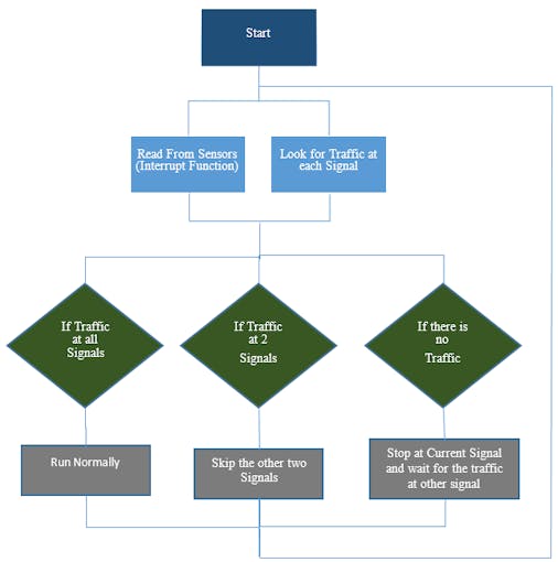
Working of Density Based Traffic Light Controller Using ArduinoThe working of the project is divided into three steps
- If there is traffic at all the signals, then the system will work normally by controlling the signals one by one.
- If there is no traffic near a signal, then the system will skip this signal and will move on to the next one. For example, if there is no vehicle at signal 2, 3 and currently the system is allowing vehicles at signal 1 to pass. Then after signal 1, the system will move on to signal 4 skipping signal 2 and 3.
- If there is no traffic at all the 4 signals, system will stop at the current signal and will only move on the next signal if there will be traffic at any other signal.
The components you are going to require for this project are as follows
- Arduino Mega 2560
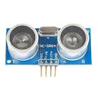
- 4 X HC-SR04 ultrasonic sensors
- 4 X Red LEDs
- 4 X Green LEDs
- 4 X Yellow LEDs
- 12 X 220 ohm resistors
- Jumper cables
- Breadboards
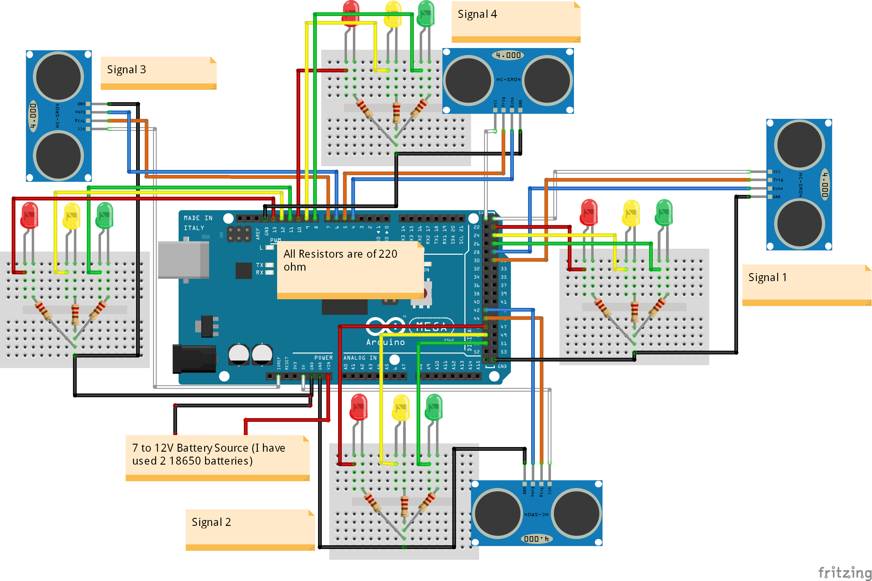
Four ultrasonic sensors are interfaced with the Arduino. Arduino will read from these sensors and will calculate the distance. This sensor can measure from 2 to 400 cm.
Ultrasonic sensor basically emits an ultrasonic wave from the trigger and it is received by the echo after deflecting an object. In order to generate a wave, we will have to set the trigger at high for 10 us which will send an 8 cycle sonic burst at 40 KHz which will hit the object and after hitting the object, the wave will be received by the echo. The echo will then tell us the time that the wave have traveled in us (micro seconds). We will then convert this time into distance travelled by using S = v*t.
Read More: Ultrasonic sensor HC-SR04 interfacing with Arduino
LED’s are connected to the Arduino through the 220 ohm resistors. It is necessary to use the resistor with the LED. The resistor limits the current flowing through the LED. If you won’t use it then the LED will burn out soon. You can use the resistor of value from 100 ohm to 10k ohm with the LED. Larger the value of LED, lesser the current will pass.
Read More: Interfacing LED with Arduino

First of all, we included the timerone library. This library is used to repetitively measure a period of time in microseconds and at the end of each period, an interrupt function will be called.
We have used this library because we want to read from the sensors and control LED’s at the same time. We will have to use the delay in between the traffic signal so we can’t read from the sensors continuously. Therefore we have used this library which will allow us to call a function in which we will read from the sensors continuously and in the loop function, we will control the traffic signals.
#include<TimerOne.h>In the setup function, we have used the Timer1.initialize(microseconds) function. This must be called before you use any of the other methods of timerone library. “Microseconds” is actually the period of time the timer takes. It is optionally to specify the timer’s period here. The default period is 1 second. Keep in mind that it breaks analogWrite() on digital pins 9 and 10.
Timer1.initialize(100000);Timer1.attachInterrupt(softInterr) calls a function each time the timer period finishes. We have set the timer period at 100000 so our function will be called after 100 milli seconds.
Timer1.attachInterrupt(softInterr);In the loop function it is looking if there is any vehicles under the 5 cm distance or not. If there will be vehicle, then the function to that signal will be called.
void loop()
{
 // If there are vehicles at signal 1
 if(S1<t)
 {
 signal1Function();
 }
 // If there are vehicles at signal 2
 if(S2<t)
 {
 signal2Function();
 }
 // If there are vehicles at signal 3
 if(S3<t)
 {
 signal3Function();
 }
 // If there are vehicles at signal 4
 if(S4<t)
 {
 signal4Function();
 }
}
‘Softinterr()’ is the interrupt function and it will called after every 100 milliseconds. In this function, we have read from the ultrasonic sensors and have calculated the distance.
void softInterr()
{
 // Reading from first ultrasonic sensor
 digitalWrite(triggerpin1, LOW);
 delayMicroseconds(2);
 digitalWrite(triggerpin1, HIGH);
 delayMicroseconds(10);
 digitalWrite(triggerpin1, LOW);
 time = pulseIn(echopin1, HIGH);
S1= time*0.034/2;The Arduino code for density based traffic light controller using Arduino is as follows
#include<TimerOne.h>
int signal1[] = {23, 25, 27};
int signal2[] = {46, 48, 50};
int signal3[] = {13, 12, 11};
int signal4[] = {10, 9, 8};
int redDelay = 5000;
int yellowDelay = 2000;
volatile int triggerpin1 = 31;
volatile int echopin1 = 29;
volatile int triggerpin2 = 44;
volatile int echopin2 = 42;
volatile int triggerpin3 = 7;
volatile int echopin3 = 6;
volatile int triggerpin4 = 5;
volatile int echopin4 = 4;
volatile long time; // Variable for storing the time traveled
volatile int S1, S2, S3, S4; // Variables for storing the distance covered
int t = 5; // distance under which it will look for vehicles.
void setup(){
 Serial.begin(115200);
 Timer1.initialize(100000); //Begin using the timer. This function must be called first. "microseconds" is the period of time the timer takes.
 Timer1.attachInterrupt(softInterr); //Run a function each time the timer period finishes.
 // Declaring LED pins as output
 for(int i=0; i<3; i++){
 pinMode(signal1[i], OUTPUT);
 pinMode(signal2[i], OUTPUT);
 pinMode(signal3[i], OUTPUT);
 pinMode(signal4[i], OUTPUT);
 }
 // Declaring ultrasonic sensor pins as output
 pinMode(triggerpin1, OUTPUT);
 pinMode(echopin1, INPUT);
 pinMode(triggerpin2, OUTPUT);
 pinMode(echopin2, INPUT);
 pinMode(triggerpin3, OUTPUT);
 pinMode(echopin3, INPUT);
 pinMode(triggerpin4, OUTPUT);
 pinMode(echopin4, INPUT);
}
void loop()
{
 // If there are vehicles at signal 1
 if(S1<t)
 {
 signal1Function();
 }
 // If there are vehicles at signal 2
 if(S2<t)
 {
 signal2Function();
 }
 // If there are vehicles at signal 3
 if(S3<t)
 {
 signal3Function();
 }
 // If there are vehicles at signal 4
 if(S4<t)
 {
 signal4Function();
 }
}
// This is interrupt function and it will run each time the timer period finishes. The timer period is set at 100 milli seconds.
void softInterr()
{
 // Reading from first ultrasonic sensor
 digitalWrite(triggerpin1, LOW);
 delayMicroseconds(2);
 digitalWrite(triggerpin1, HIGH);
 delayMicroseconds(10);
 digitalWrite(triggerpin1, LOW);
 time = pulseIn(echopin1, HIGH);
 S1= time*0.034/2;
 // Reading from second ultrasonic sensor
 digitalWrite(triggerpin2, LOW);
 delayMicroseconds(2);
 digitalWrite(triggerpin2, HIGH);
 delayMicroseconds(10);
 digitalWrite(triggerpin2, LOW);
 time = pulseIn(echopin2, HIGH);
 S2= time*0.034/2;
 // Reading from third ultrasonic sensor
 digitalWrite(triggerpin3, LOW);
 delayMicroseconds(2);
 digitalWrite(triggerpin3, HIGH);
 delayMicroseconds(10);
 digitalWrite(triggerpin3, LOW);
 time = pulseIn(echopin3, HIGH);
 S3= time*0.034/2;
 // Reading from fourth ultrasonic sensor
 digitalWrite(triggerpin4, LOW);
 delayMicroseconds(2);
 digitalWrite(triggerpin4, HIGH);
 delayMicroseconds(10);
 digitalWrite(triggerpin4, LOW);
 time = pulseIn(echopin4, HIGH);
 S4= time*0.034/2;
 // Print distance values on serial monitor for debugging
 Serial.print("S1: ");
 Serial.print(S1);
 Serial.print(" S2: ");
 Serial.print(S2);
 Serial.print(" S3: ");
 Serial.print(S3);
 Serial.print(" S4: ");
 Serial.println(S4);
}
void signal1Function()
{
 Serial.println("1");
 low();
 // Make RED LED LOW and make Green HIGH for 5 seconds
 digitalWrite(signal1[0], LOW);
 digitalWrite(signal1[2], HIGH);
 delay(redDelay);
 // if there are vehicels at other signals
 if(S2<t || S3<t || S4<t)
 {
 // Make Green LED LOW and make yellow LED HIGH for 2 seconds
 digitalWrite(signal1[2], LOW);
 digitalWrite(signal1[1], HIGH);
 delay(yellowDelay);
 }
}
void signal2Function()
{
 Serial.println("2");
 low();
 digitalWrite(signal2[0], LOW);
 digitalWrite(signal2[2], HIGH);
 delay(redDelay);

 if(S1<t || S3<t || S4<t)
 {
 digitalWrite(signal2[2], LOW);
 digitalWrite(signal2[1], HIGH);
 delay(yellowDelay);
 }
}
void signal3Function()
{
 Serial.println("3");
 low();
 digitalWrite(signal3[0], LOW);
 digitalWrite(signal3[2], HIGH);
 delay(redDelay);
 if(S1<t || S2<t || S4<t)
 {
 digitalWrite(signal3[2], LOW);
 digitalWrite(signal3[1], HIGH);
 delay(yellowDelay);
 }
}
void signal4Function()
{
 Serial.println("4");
 low();
 digitalWrite(signal4[0], LOW);
 digitalWrite(signal4[2], HIGH);
 delay(redDelay);
 if(S1<t || S2<t || S3<t)
 {
 digitalWrite(signal4[2], LOW);
 digitalWrite(signal4[1], HIGH);
 delay(yellowDelay);
 }
}
// Function to make all LED's LOW except RED one's.
void low()
{
 for(int i=1; i<3; i++)
 {
 digitalWrite(signal1[i], LOW);
 digitalWrite(signal2[i], LOW);
 digitalWrite(signal3[i], LOW);
 digitalWrite(signal4[i], LOW);
 }
 for(int i=0; i<1; i++)
 {
 digitalWrite(signal1[i], HIGH);
 digitalWrite(signal2[i], HIGH);
 digitalWrite(signal3[i], HIGH);
 digitalWrite(signal4[i], HIGH);
 }
}We will update this system with when a vehicle try to move even during red signal it will turn on an alarm to warn the driver of the vehicle and will send the alert to the traffic warden with the picture.
If you have any future recommendations, please do ask in the comment section.

In previous post, we built an Arduino Traffic Light Controller and in this post, you are going to learn about how to make an density based traffic light controller using Arduino. The main purpose of this project is, if there will be no traffic on the other signal, one shouldn’t wait for that signal. The system will skip that signal and will move on the next one.
Arduino is the main part of this project and it will be used to read from ultrasonic sensor HC-SR04 and calculate the distance. This distance will tell us if any vehicle is near the signal or not and according to that the traffic signals will be controlled.
The main task was to avoid use of delay because we have to continuously read from the ultrasonic sensors and also at the same time, we have to control signals which requires the use of delay function.
So we have used the timerone library which is used to repetitively measure a period of time in microseconds and at the end of each period, an interrupt function will be called. In this function, we will read from the sensors and in the loop function, we will control the traffic signals.
For Custom Projects, hire me at https://www.freelancer.com/u/Muhammadaqibdutt
Working of Density Based Traffic Light Controller Using ArduinoThe working of the project is divided into three steps
- If there is traffic at all the signals, then the system will work normally by controlling the signals one by one.
- If there is no traffic near a signal, then the system will skip this signal and will move on to the next one. For example, if there is no vehicle at signal 2, 3 and currently the system is allowing vehicles at signal 1 to pass. Then after signal 1, the system will move on to signal 4 skipping signal 2 and 3.
- If there is no traffic at all the 4 signals, system will stop at the current signal and will only move on the next signal if there will be traffic at any other signal.
The components you are going to require for this project are as follows
- Arduino Mega 2560
- 4 X HC-SR04 ultrasonic sensors
- 4 X Red LEDs
- 4 X Green LEDs
- 4 X Yellow LEDs
- 12 X 220 ohm resistors
- Jumper cables
- Breadboards
Four ultrasonic sensors are interfaced with the Arduino. Arduino will read from these sensors and will calculate the distance. This sensor can measure from 2 to 400 cm.
Ultrasonic sensor basically emits an ultrasonic wave from the trigger and it is received by the echo after deflecting an object. In order to generate a wave, we will have to set the trigger at high for 10 us which will send an 8 cycle sonic burst at 40 KHz which will hit the object and after hitting the object, the wave will be received by the echo. The echo will then tell us the time that the wave have traveled in us (micro seconds). We will then convert this time into distance travelled by using S = v*t.
Read More: Ultrasonic sensor HC-SR04 interfacing with Arduino
LED’s are connected to the Arduino through the 220 ohm resistors. It is necessary to use the resistor with the LED. The resistor limits the current flowing through the LED. If you won’t use it then the LED will burn out soon. You can use the resistor of value from 100 ohm to 10k ohm with the LED. Larger the value of LED, lesser the current will pass.
Read More: Interfacing LED with Arduino
First of all, we included the timerone library. This library is used to repetitively measure a period of time in microseconds and at the end of each period, an interrupt function will be called.
We have used this library because we want to read from the sensors and control LED’s at the same time. We will have to use the delay in between the traffic signal so we can’t read from the sensors continuously. Therefore we have used this library which will allow us to call a function in which we will read from the sensors continuously and in the loop function, we will control the traffic signals.
#include<TimerOne.h>In the setup function, we have used the Timer1.initialize(microseconds) function. This must be called before you use any of the other methods of timerone library. “Microseconds” is actually the period of time the timer takes. It is optionally to specify the timer’s period here. The default period is 1 second. Keep in mind that it breaks analogWrite() on digital pins 9 and 10.
Timer1.initialize(100000);Timer1.attachInterrupt(softInterr) calls a function each time the timer period finishes. We have set the timer period at 100000 so our function will be called after 100 milli seconds.
Timer1.attachInterrupt(softInterr);In the loop function it is looking if there is any vehicles under the 5 cm distance or not. If there will be vehicle, then the function to that signal will be called.
void loop()
{
  // If there are vehicles at signal 1
  if(S1<t)
  {
    signal1Function();
  }
  // If there are vehicles at signal 2
  if(S2<t)
  {
    signal2Function();
  }
  // If there are vehicles at signal 3
  if(S3<t)
  {
    signal3Function();
  }
  // If there are vehicles at signal 4
  if(S4<t)
  {
    signal4Function();
  }
}
‘Softinterr()’ is the interrupt function and it will called after every 100 milliseconds. In this function, we have read from the ultrasonic sensors and have calculated the distance.
void softInterr()
{
  // Reading from first ultrasonic sensor
  digitalWrite(triggerpin1, LOW);
  delayMicroseconds(2);
  digitalWrite(triggerpin1, HIGH);
  delayMicroseconds(10);
  digitalWrite(triggerpin1, LOW);
  time = pulseIn(echopin1, HIGH);
S1= time*0.034/2;The Arduino code for density based traffic light controller using Arduino is as follows
#include<TimerOne.h>
int signal1[] = {23, 25, 27};
int signal2[] = {46, 48, 50};
int signal3[] = {13, 12, 11};
int signal4[] = {10, 9, 8};
int redDelay = 5000;
int yellowDelay = 2000;
volatile int triggerpin1 = 31;
volatile int echopin1 = 29;
volatile int triggerpin2 = 44;
volatile int echopin2 = 42;
volatile int triggerpin3 = 7;
volatile int echopin3 = 6;
volatile int triggerpin4 = 5;
volatile int echopin4 = 4;
volatile long time;                    // Variable for storing the time traveled
volatile int S1, S2, S3, S4;           // Variables for storing the distance covered
int t = 5;  // distance under which it will look for vehicles.
void setup(){
  Serial.begin(115200);
  Timer1.initialize(100000);  //Begin using the timer. This function must be called first. "microseconds" is the period of time the timer takes.
  Timer1.attachInterrupt(softInterr); //Run a function each time the timer period finishes.
  // Declaring LED pins as output
  for(int i=0; i<3; i++){
    pinMode(signal1[i], OUTPUT);
    pinMode(signal2[i], OUTPUT);
    pinMode(signal3[i], OUTPUT);
    pinMode(signal4[i], OUTPUT);
  }
  // Declaring ultrasonic sensor pins as output
  pinMode(triggerpin1, OUTPUT);
  pinMode(echopin1, INPUT);
  pinMode(triggerpin2, OUTPUT);
  pinMode(echopin2, INPUT);
  pinMode(triggerpin3, OUTPUT);
  pinMode(echopin3, INPUT);
  pinMode(triggerpin4, OUTPUT);
  pinMode(echopin4, INPUT);
}
void loop()
{
  // If there are vehicles at signal 1
  if(S1<t)
  {
    signal1Function();
  }
  // If there are vehicles at signal 2
  if(S2<t)
  {
    signal2Function();
  }
  // If there are vehicles at signal 3
  if(S3<t)
  {
    signal3Function();
  }
  // If there are vehicles at signal 4
  if(S4<t)
  {
    signal4Function();
  }
}
// This is interrupt function and it will run each time the timer period finishes. The timer period is set at 100 milli seconds.
void softInterr()
{
  // Reading from first ultrasonic sensor
  digitalWrite(triggerpin1, LOW);
  delayMicroseconds(2);
  digitalWrite(triggerpin1, HIGH);
  delayMicroseconds(10);
  digitalWrite(triggerpin1, LOW);
  time = pulseIn(echopin1, HIGH);
  S1= time*0.034/2;
  // Reading from second ultrasonic sensor
  digitalWrite(triggerpin2, LOW);
  delayMicroseconds(2);
  digitalWrite(triggerpin2, HIGH);
  delayMicroseconds(10);
  digitalWrite(triggerpin2, LOW);
  time = pulseIn(echopin2, HIGH);
  S2= time*0.034/2;
  // Reading from third ultrasonic sensor
  digitalWrite(triggerpin3, LOW);
  delayMicroseconds(2);
  digitalWrite(triggerpin3, HIGH);
  delayMicroseconds(10);
  digitalWrite(triggerpin3, LOW);
  time = pulseIn(echopin3, HIGH);
  S3= time*0.034/2;
  // Reading from fourth ultrasonic sensor
  digitalWrite(triggerpin4, LOW);
  delayMicroseconds(2);
  digitalWrite(triggerpin4, HIGH);
  delayMicroseconds(10);
  digitalWrite(triggerpin4, LOW);
  time = pulseIn(echopin4, HIGH);
  S4= time*0.034/2;
  // Print distance values on serial monitor for debugging
  Serial.print("S1: ");
  Serial.print(S1);
  Serial.print("  S2: ");
  Serial.print(S2);
  Serial.print("  S3: ");
  Serial.print(S3);
  Serial.print("  S4: ");
  Serial.println(S4);
}
void signal1Function()
{
  Serial.println("1");
  low();
  // Make RED LED LOW and make Green HIGH for 5 seconds
  digitalWrite(signal1[0], LOW);
  digitalWrite(signal1[2], HIGH);
  delay(redDelay);
  // if there are vehicels at other signals
  if(S2<t || S3<t || S4<t)
  {
    // Make Green LED LOW and make yellow LED HIGH for 2 seconds
    digitalWrite(signal1[2], LOW);
    digitalWrite(signal1[1], HIGH);
    delay(yellowDelay);
  }
}
void signal2Function()
{
  Serial.println("2");
  low();
  digitalWrite(signal2[0], LOW);
  digitalWrite(signal2[2], HIGH);
  delay(redDelay);

  if(S1<t || S3<t || S4<t)
  {
    digitalWrite(signal2[2], LOW);
    digitalWrite(signal2[1], HIGH);
    delay(yellowDelay);
  }
}
void signal3Function()
{
  Serial.println("3");
  low();
  digitalWrite(signal3[0], LOW);
  digitalWrite(signal3[2], HIGH);
  delay(redDelay);
  if(S1<t || S2<t || S4<t)
  {
    digitalWrite(signal3[2], LOW);
    digitalWrite(signal3[1], HIGH);
    delay(yellowDelay);
  }
}
void signal4Function()
{
  Serial.println("4");
  low();
  digitalWrite(signal4[0], LOW);
  digitalWrite(signal4[2], HIGH);
  delay(redDelay);
  if(S1<t || S2<t || S3<t)
  {
    digitalWrite(signal4[2], LOW);
    digitalWrite(signal4[1], HIGH);
    delay(yellowDelay);
  }
}
// Function to make all LED's LOW except RED one's.
void low()
{
  for(int i=1; i<3; i++)
  {
    digitalWrite(signal1[i], LOW);
    digitalWrite(signal2[i], LOW);
    digitalWrite(signal3[i], LOW);
    digitalWrite(signal4[i], LOW);
  }
  for(int i=0; i<1; i++)
  {
    digitalWrite(signal1[i], HIGH);
    digitalWrite(signal2[i], HIGH);
    digitalWrite(signal3[i], HIGH);
    digitalWrite(signal4[i], HIGH);
  }
}We will update this system with when a vehicle try to move even during red signal it will turn on an alarm to warn the driver of the vehicle and will send the alert to the traffic warden with the picture.
If you have any future recommendations, please do ask in the comment section.