Digital Watch on Arduino Using a Finite State Machine © GPL3+
DESCRIPTION
Hey there,
I'm going to show you how a digital watch can be created with YAKINDU Statechart Tools and run on an Arduino, which uses a LCD Keypad Shield.
The original model of the digital watch was taken from David Harel. He has published a paper about the "broad extension of the conventional formalism of state machines and state diagrams."
In this paper he used the example of the digital watch for his research. I've used it as an inspiration and rebuilt the watch with YAKINDU Statechart Tools (a tool for creating graphical models of state machines and generate C/C++ code with it) and brought it back to life on an Arduino.
How the Digital Watch Works
Let's start by defining how the digital watch should work. Do you remember these... let's say... "ultra cool" digital watches everyone had back in the 90's? An integrated stopwatch, different alarms and its annoying beep every full hour. If don't, have a look: 90's digital watch.
So basically it's a configurable watch with different modes. Mainly, the current time will be displayed, but there are some other features. As input you've got an on/off, a mode and a set button. Additionally, you can turn the light on and off.
With the mode button you can distinguish between the modes and activate/disable the clock features:
- Display the time (Clock)
- Display the date (Date)
- Set the alarm (Alarm 1, Alarm 2)
- Enable/disable chime (Set Chime)
- Use the stopwatch (Stop Watch)
Within the menus you can use the on/off button to configure the mode. The set button allows you to set the time - e.g. for the clock or the alarms. The stopwatch can be controlled - started and stopped - by using the light on and light off button. You can also use an integrated lap counter.
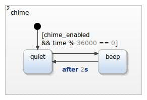
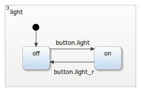
Furthermore, there is a chime, which bells every full our, and a controllable backlight integrated. At the first step I did not wired them to the Arduino.
The State Machine
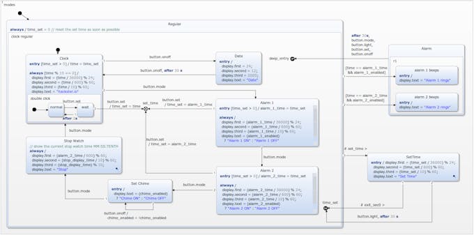
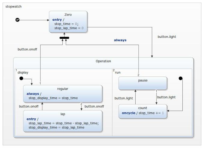
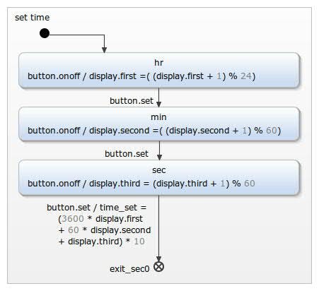
I don't want to go to much in detail for the explanation of this example. It's not because it's too complex, it's just a little bit too large. I will try to explain the basic idea of how it works. The execution should be self-explaining, by having a look at the model or download and simulate it. Some parts of the state machine are sum up in sub regions, like the set time region. With this the readability of the state machine should be ensured.
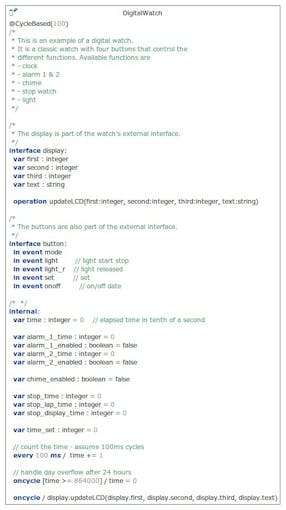
The model is split up into two parts - a graphical and a textual. In the textual part the events, variables, etc. will be defined. In the graphical part - the state diagram - the logical execution of the model is specified. To create a state machine, that fulfills the specified behavior, some input events are required, which can be used in the model: onoff, set, mode, light, and light_r. Within the definition section an internal event is used, which increments the time value every 100 ms:
every 100 ms / time += 1Based on the 100 ms steps the current time will be calculated in the HH:MM:SS format:
display.first = (time / 36000) % 24;
display.second = (time / 600) % 60;
display.third = (time / 10) % 60;
The values will be wired to the LCD display by using the operation updateLCD every time the state machine will be called:
display.updateLCD(display.first, display.second, display.third, display.text)The basic execution of the state machine is already defined in the section How the Digital Watch work. Within the tool I've used some "special" modeling elements like CompositeState, History, Sub-Diagrams, ExitNodes, etc.. A detailed description can be found in the User Guide.
LCD Keypad Shield
The LCD Keypad Shield is quite cool for simple projects, which require a screen for visualization and some buttons as input - a typical, simple HMI (Human Machine Interface). The LCD Keypad Shield contains five user buttons and another one for reset. The five buttons all together are connected to the A0 pin of the Arduino. Each of them is connected to a voltage divider, which allows to distinguish between the buttons.
You can use analogRead(0) to find the specific values, which can of course differ by the manufacturer. This simple project displays the current value on the LCD:
#include <Arduino.h>
#include <LiquidCrystal.h>

LiquidCrystal lcd(8, 9, 4, 5, 6, 7);

void setup() {
 lcd.begin(16, 2);
 lcd.setCursor(0,0);
 lcd.write("Measured Value");
}

void loop() {
 lcd.setCursor(0,1);
 lcd.print(" ");
 lcd.setCursor(0,1);
 lcd.print(analogRead(0));
 delay(200);
}
These are my measured results:
- None: 1023
- Select: 640
- Left: 411
- Down: 257
- Up: 100
- Right: 0

With these thresholds it's possible to read the buttons:
#define NONE 0
#define SELECT 1
#define LEFT 2
#define DOWN 3
#define UP 4
#define RIGHT 5

static int readButton() {
 int result = 0;
 result = analogRead(0);
 if (result < 50) {
 return RIGHT;
 }
 if (result < 150) {
 return UP;
 }
 if (result < 300) {
 return DOWN;
 }
 if (result < 550) {
 return LEFT;
 }
 if (result < 850) {
 return SELECT;
 }
 return NONE;
}
Interfacing the State Machine
The generated C++ code of the state machine provides interfaces, which must be implemented to control the state machine. The first step is connecting the in events with the keys of the Keypad Shield. I've already shown how to read the buttons, but for interfacing them to the state machine, debouncing the buttons is required - otherwise the events would be raised multiple times, which results in unpredictable behavior. The concept of software debouncing is not new. You can have a look at the Arduino documentation.
In my implementation I detect a falling edge (releasing the button). I read the value of the button, wait for 80 ms (got better results with 80 instead of 50), save the result and read the new value. If the oldResult was not NONE (unpressed) and the new result is NONE, I know, that the button has been pressed before and now has been released. Then, I raise the according input event of the state machine.
int oldState = NONE;
static void raiseEvents() {
 int buttonPressed = readButton();
 delay(80);
 oldState = buttonPressed;
 if (oldState != NONE && readButton() == NONE) {
 switch (oldState) {
 case SELECT: {
 stateMachine->getSCI_Button()->raise_mode();
 break;
 }
 case LEFT: {
 stateMachine->getSCI_Button()->raise_set();
 break;
 }
 case DOWN: {
 stateMachine->getSCI_Button()->raise_light();
 break;
 }
 case UP: {
 stateMachine->getSCI_Button()->raise_light_r();
 break;
 }
 case RIGHT: {
 stateMachine->getSCI_Button()->raise_onoff();
 break;
 }
 default: {
 break;
 }
 }
 }
}
Wiring Things Together
The main program uses three parts:
- The State Machine
- A Timer
- A Display Handler (typical lcd.print(...))
DigitalWatch* stateMachine = new DigitalWatch();
CPPTimerInterface* timer_sct = new CPPTimerInterface();
DisplayHandler* displayHandler = new DisplayHandler();
The state machine uses a display handler and got a timer, which will be updated to control the timed events. Afterwards, the state machine gets initialized and entered.
void setup() {
 stateMachine->setSCI_Display_OCB(displayHandler);
 stateMachine->setTimer(timer_sct);
 stateMachine->init();
 stateMachine->enter();
}
The loop does three things:
- Raise input events
- Calculate the elapsed time and update the timer
- Call the state machine
long current_time = 0;
long last_cycle_time = 0;
void loop() {
 raiseEvents();
 last_cycle_time = current_time;
 current_time = millis();
 timer_sct->updateActiveTimer(stateMachine,
 current_time - last_cycle_time);
 stateMachine->runCycle();
}
Get the Example
That's it. Probably, I've not mentioned every detail of the implementation, but you can have a look at the example or leave a comment.
Add the example to a running IDE with:
File -> New -> Example -> YAKINDU Statechart Examples -> Next -> Arduino - Digital Watch (C++)
>> You can download the IDE here <<
You can start with a 30 days trial. Afterwards, you must get a license, which is free for non-commercial use!
 |
| × | 1 | |||
| × | 1 |
Hey there,
I'm going to show you how a digital watch can be created with YAKINDU Statechart Tools and run on an Arduino, which uses a LCD Keypad Shield.
The original model of the digital watch was taken from David Harel. He has published a paper about the "broad extension of the conventional formalism of state machines and state diagrams."
In this paper he used the example of the digital watch for his research. I've used it as an inspiration and rebuilt the watch with YAKINDU Statechart Tools (a tool for creating graphical models of state machines and generate C/C++ code with it) and brought it back to life on an Arduino.
How the Digital Watch Works
Let's start by defining how the digital watch should work. Do you remember these... let's say... "ultra cool" digital watches everyone had back in the 90's? An integrated stopwatch, different alarms and its annoying beep every full hour. If don't, have a look: 90's digital watch.
So basically it's a configurable watch with different modes. Mainly, the current time will be displayed, but there are some other features. As input you've got an on/off, a mode and a set button. Additionally, you can turn the light on and off.
With the mode button you can distinguish between the modes and activate/disable the clock features:
- Display the time (Clock)
- Display the date (Date)
- Set the alarm (Alarm 1, Alarm 2)
- Enable/disable chime (Set Chime)
- Use the stopwatch (Stop Watch)
Within the menus you can use the on/off button to configure the mode. The set button allows you to set the time - e.g. for the clock or the alarms. The stopwatch can be controlled - started and stopped - by using the light on and light off button. You can also use an integrated lap counter.
Furthermore, there is a chime, which bells every full our, and a controllable backlight integrated. At the first step I did not wired them to the Arduino.
The State Machine
I don't want to go to much in detail for the explanation of this example. It's not because it's too complex, it's just a little bit too large. I will try to explain the basic idea of how it works. The execution should be self-explaining, by having a look at the model or download and simulate it. Some parts of the state machine are sum up in sub regions, like the set time region. With this the readability of the state machine should be ensured.
The model is split up into two parts - a graphical and a textual. In the textual part the events, variables, etc. will be defined. In the graphical part - the state diagram - the logical execution of the model is specified. To create a state machine, that fulfills the specified behavior, some input events are required, which can be used in the model: onoff, set, mode, light, and light_r. Within the definition section an internal event is used, which increments the time value every 100 ms:
every 100 ms / time += 1Based on the 100 ms steps the current time will be calculated in the HH:MM:SS format:
display.first = (time / 36000) % 24;
display.second = (time / 600) % 60;
display.third = (time / 10) % 60;
The values will be wired to the LCD display by using the operation updateLCD every time the state machine will be called:
display.updateLCD(display.first, display.second, display.third, display.text)The basic execution of the state machine is already defined in the section How the Digital Watch work. Within the tool I've used some "special" modeling elements like CompositeState, History, Sub-Diagrams, ExitNodes, etc.. A detailed description can be found in the User Guide.
LCD Keypad Shield
The LCD Keypad Shield is quite cool for simple projects, which require a screen for visualization and some buttons as input - a typical, simple HMI (Human Machine Interface). The LCD Keypad Shield contains five user buttons and another one for reset. The five buttons all together are connected to the A0 pin of the Arduino. Each of them is connected to a voltage divider, which allows to distinguish between the buttons.
You can use analogRead(0) to find the specific values, which can of course differ by the manufacturer. This simple project displays the current value on the LCD:
#include <Arduino.h>
#include <LiquidCrystal.h>

LiquidCrystal lcd(8, 9, 4, 5, 6, 7);

void setup() {
    lcd.begin(16, 2);
    lcd.setCursor(0,0);
    lcd.write("Measured Value");
}

void loop() {
    lcd.setCursor(0,1);
    lcd.print("    ");
    lcd.setCursor(0,1);
    lcd.print(analogRead(0));
    delay(200);
}
These are my measured results:
- None: 1023
- Select: 640
- Left: 411
- Down: 257
- Up: 100
- Right: 0
With these thresholds it's possible to read the buttons:
#define NONE 0
#define SELECT 1
#define LEFT 2
#define DOWN 3
#define UP 4
#define RIGHT 5

static int readButton() {
    int result = 0;
    result = analogRead(0);
    if (result < 50) {
        return RIGHT;
    }
    if (result < 150) {
        return UP;
    }
    if (result < 300) {
        return DOWN;
    }
    if (result < 550) {
        return LEFT;
    }
    if (result < 850) {
        return SELECT;
    }
    return NONE;
}
Interfacing the State Machine
The generated C++ code of the state machine provides interfaces, which must be implemented to control the state machine. The first step is connecting the in events with the keys of the Keypad Shield. I've already shown how to read the buttons, but for interfacing them to the state machine, debouncing the buttons is required - otherwise the events would be raised multiple times, which results in unpredictable behavior. The concept of software debouncing is not new. You can have a look at the Arduino documentation.
In my implementation I detect a falling edge (releasing the button). I read the value of the button, wait for 80 ms (got better results with 80 instead of 50), save the result and read the new value. If the oldResult was not NONE (unpressed) and the new result is NONE, I know, that the button has been pressed before and now has been released. Then, I raise the according input event of the state machine.
int oldState = NONE;
static void raiseEvents() {
    int buttonPressed = readButton();
    delay(80);
    oldState = buttonPressed;
    if (oldState != NONE && readButton() == NONE) {
        switch (oldState) {
            case SELECT: {
                stateMachine->getSCI_Button()->raise_mode();
                break;
            }
            case LEFT: {
                stateMachine->getSCI_Button()->raise_set();
                break;
            }
            case DOWN: {
                stateMachine->getSCI_Button()->raise_light();
                break;
            }
            case UP: {
                stateMachine->getSCI_Button()->raise_light_r();
                break;
            }
            case RIGHT: {
                stateMachine->getSCI_Button()->raise_onoff();
                break;
            }
            default: {
                break;
            }
        }
    }
}
Wiring Things Together
The main program uses three parts:
- The State Machine
- A Timer
- A Display Handler (typical lcd.print(...))
DigitalWatch* stateMachine = new DigitalWatch();
CPPTimerInterface* timer_sct = new CPPTimerInterface();
DisplayHandler* displayHandler = new DisplayHandler();
The state machine uses a display handler and got a timer, which will be updated to control the timed events. Afterwards, the state machine gets initialized and entered.
void setup() {
    stateMachine->setSCI_Display_OCB(displayHandler);
    stateMachine->setTimer(timer_sct);
    stateMachine->init();
    stateMachine->enter();
}
The loop does three things:
- Raise input events
- Calculate the elapsed time and update the timer
- Call the state machine
long current_time = 0;
long last_cycle_time = 0;
void loop() {
    raiseEvents();
    last_cycle_time = current_time;
    current_time = millis();
    timer_sct->updateActiveTimer(stateMachine,
        current_time - last_cycle_time);
    stateMachine->runCycle();
}
Get the Example
That's it. Probably, I've not mentioned every detail of the implementation, but you can have a look at the example or leave a comment.
Add the example to a running IDE with:
File -> New -> Example -> YAKINDU Statechart Examples -> Next -> Arduino - Digital Watch (C++)
>> You can download the IDE here <<
You can start with a 30 days trial. Afterwards, you must get a license, which is free for non-commercial use!