DIY pH Dosing Pump © CC BY-NC
DESCRIPTION
We will be making a pH dosing system. It has the capability of maintaining the sample within a defined pH range, in this case, 8-8.5. If the readings go out of range, small amounts of either pH UP or pH DOWN solution is automatically added to the sample until the readings return within the limits. The pH level will be monitored by the EZO pH sensor while the UP/DOWN solutions will be dispensed using peristaltic pumps. Operation is via I2C protocol and readings are displayed on the Arduino serial monitor
Step 1: Pre-assembly Requirements
a) Calibrate pH sensor and pumps. For the calibration process refer to the following: pH calibration, pump calibration.
b) Set the pH sensor and pumps protocol to I2C and each device needs a unique I2C address. In accordance with the sample code for this project, the following addresses are used: pH sensor address is 99, pump for pH UP solution is 103 and pump for pH DOWN solution is 104. For information on how to change between modes and set addresses, refer to this LINK.
The calibration and the switch to I2C MUST be done before implementing the sensors into this project.
Step 2: Assemble Hardware

Connect the hardware as shown in the schematic.
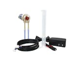
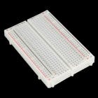
The peristaltic pump has two power lines. The line that goes to the Arduino's 5V pin is for the circuitry attached to the pump while the external 12V supply is for the pump itself. The five pin headers are used to mount the data cables of the pumps to the breadboard after which jumper wires make the appropriate connections to the Arduino.
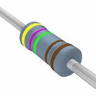
The two 4.7kΩ resistors serve as pull up resistors for the SDA (Serial Data) and SCL (Serial Clock) lines.
Step 3: Load Program onto Arduino
The code for this project makes use of a customized library and header file for the EZO circuits in I2C mode. You will have to add them to your Arduino IDE in order to use the code. The steps below include the process of making this addition to the IDE.
a) Download Ezo_I2c_lib, a zip folder from GitHub onto your computer.
b) On your computer, open the Arduino IDE (You can download the IDE from HERE if you do not have it).
c) In the IDE, go to Sketch -> Include Library -> Add.ZIP Library -> Select the Ezo_I2c_lib folder you just downloaded. The appropriate files are now included.
d) Copy the code from pH_dosing_pump onto your Arduino work panel. You can also access this code from the Ezo_I2c_lib folder downloaded above.
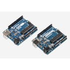
e) Compile and upload the pH_dosing_pump code to your Arduino UNO.
f) Readings are displayed on the serial monitor. To open the serial monitor, go to Tools -> Serial Monitor or press Ctrl+Shift+M on your keyboard. Set the baud rate to 9600 and select "Carriage return". The pH readings should display and the pumps will be triggered accordingly to dispense pH UP and pH DOWN solution. Remember this sample code takes into consideration the pH between 8-8.5, so the pumps will only turn on when out of this range.
Demonstration
The goal of the demonstration is to show the maintenance of the pH level of the sample between 8-8.5. In the setup, the sample is in the largest beaker at the center. The pH UP solution is in the left beaker while pH DOWN is in the right. Because of the small sample amount being monitored, the UP and DOWN solutions were diluted so that changes in pH level of the sample are not drastic as they are added. Throughout the process, there are a few back and forths in the addition of the pH UP and DOWN solutions until the readings stabilize at pH = 8.33 which is within the desired range.


We will be making a pH dosing system. It has the capability of maintaining the sample within a defined pH range, in this case, 8-8.5. If the readings go out of range, small amounts of either pH UP or pH DOWN solution is automatically added to the sample until the readings return within the limits. The pH level will be monitored by the EZO pH sensor while the UP/DOWN solutions will be dispensed using peristaltic pumps. Operation is via I2C protocol and readings are displayed on the Arduino serial monitor
Step 1: Pre-assembly Requirements
a) Calibrate pH sensor and pumps. For the calibration process refer to the following: pH calibration, pump calibration.
b) Set the pH sensor and pumps protocol to I2C and each device needs a unique I2C address. In accordance with the sample code for this project, the following addresses are used: pH sensor address is 99, pump for pH UP solution is 103 and pump for pH DOWN solution is 104. For information on how to change between modes and set addresses, refer to this LINK.
The calibration and the switch to I2C MUST be done before implementing the sensors into this project.
Step 2: Assemble Hardware
Connect the hardware as shown in the schematic.
The peristaltic pump has two power lines. The line that goes to the Arduino's 5V pin is for the circuitry attached to the pump while the external 12V supply is for the pump itself. The five pin headers are used to mount the data cables of the pumps to the breadboard after which jumper wires make the appropriate connections to the Arduino.
The two 4.7kΩ resistors serve as pull up resistors for the SDA (Serial Data) and SCL (Serial Clock) lines.
Step 3: Load Program onto Arduino
The code for this project makes use of a customized library and header file for the EZO circuits in I2C mode. You will have to add them to your Arduino IDE in order to use the code. The steps below include the process of making this addition to the IDE.
a) Download Ezo_I2c_lib, a zip folder from GitHub onto your computer.
b) On your computer, open the Arduino IDE (You can download the IDE from HERE if you do not have it).
c) In the IDE, go to Sketch -> Include Library -> Add.ZIP Library -> Select the Ezo_I2c_lib folder you just downloaded. The appropriate files are now included.
d) Copy the code from pH_dosing_pump onto your Arduino work panel. You can also access this code from the Ezo_I2c_lib folder downloaded above.
e) Compile and upload the pH_dosing_pump code to your Arduino UNO.
f) Readings are displayed on the serial monitor. To open the serial monitor, go to Tools -> Serial Monitor or press Ctrl+Shift+M on your keyboard. Set the baud rate to 9600 and select "Carriage return". The pH readings should display and the pumps will be triggered accordingly to dispense pH UP and pH DOWN solution. Remember this sample code takes into consideration the pH between 8-8.5, so the pumps will only turn on when out of this range.
Demonstration
The goal of the demonstration is to show the maintenance of the pH level of the sample between 8-8.5. In the setup, the sample is in the largest beaker at the center. The pH UP solution is in the left beaker while pH DOWN is in the right. Because of the small sample amount being monitored, the UP and DOWN solutions were diluted so that changes in pH level of the sample are not drastic as they are added. Throughout the process, there are a few back and forths in the addition of the pH UP and DOWN solutions until the readings stabilize at pH = 8.33 which is within the desired range.
