Trybotics Logo

FM Radio with Frequency Display © GPL3+

DESCRIPTION

1. Goal

My goal was to make simple FM radio with a display that shows the frequency. And manual control over frequency and volume.

2. Hardware

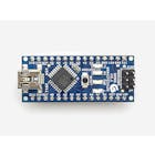
You can use Arduino Uno or Nano:

2.1 RDA5807

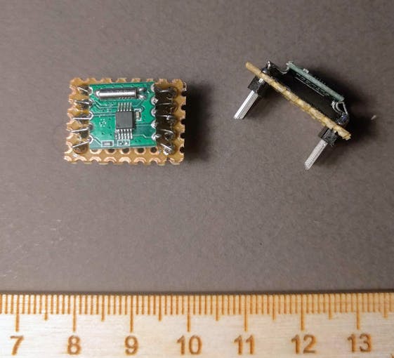
The main component is RDA5807 Sinle-Chip FM Receiver Module. It's very tiny..So you need to build some kind adapter.

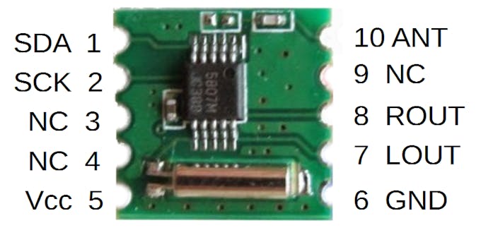
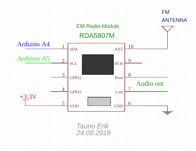
Connect RDA5807 pin 1 (SDA) to Arduino A4 and pin 2 (SCL) to Arduino A5. Pin 5 to 3.3v and pin 6 to Ground. Pin 10 is antenna. 7 is left and 8 is right audio output. The antenna may be just a piece of wire.

You can connect speaker directly to RDA5807:

Or connect to amplifier.

2.2 Amplifier

I used LM386 to make this simple mono audi amplifier:

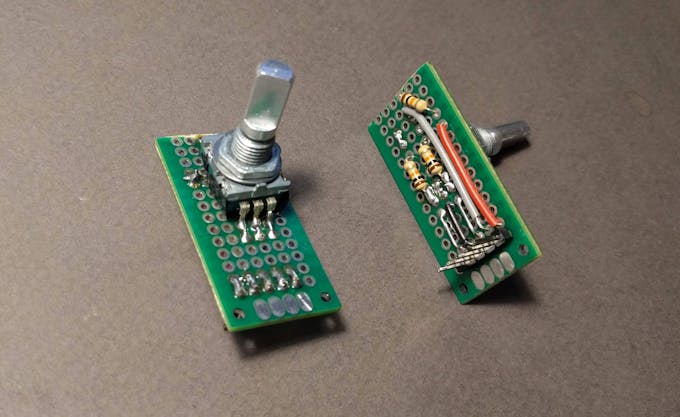
2.3 Rotary Encoder

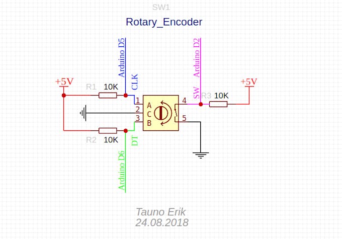
We use the Rotary Encoder to determine whether we are turning down (left) or up (right) the frequency.

2.4 7-Segment LED Display

It is easier and cheaper to buy readymade 7-segment LED module than to build it yourself.

But it is more fun to make it yourself. Like I did. There is many diffrent coloure and sizes 7-segment LEDs and they may be diffrent. So first test how it works. We need Common Cathode 7-segment LEDs. Mine looks like this:

I use MAX7219 IC to drive LEDs, but it does make a lot of electric noise. What can be heard from the speaker... Thay they that MAX7221 is better.

Connect MAX7219 DIN (Data In, leg 1) to Arduino D12, LOAD to D10 and CLK to D11.

3. Software

We use I2C protocol to communicate with RDA5807 Radio module:

#include <Wire.h> 

Define Arduino pins what we use:

/* MAX7219 LED driver */ #define MAX7219_DIN 12 #define MAX7219_CS 10 #define MAX7219_CLK 11 /* Rotary Encoder */ #define clkPin 5 #define dtPin 6 #define swPin 2 

The code how to use RDA5807 I found it here: https://github.com/lucsmall/Arduino-RDA5807M

The channel is default frequensy what radio plays when it boot up.

If Radio frequensy is 106.1 MHz. (106.1 x 10) - 870 = 191

uint16_t channel = 191; 

Address of the RDA5807 on two wire bus:

#define RDA5807M_ADDRESS 0b0010000 // 0x10 

See the code here with all coments what it means: https://github.com/lucsmall/Arduino-RDA5807M/blob/master/A20150415RDA5807FMTuner.ino

#define BOOT_CONFIG_LEN 12 #define TUNE_CONFIG_LEN 4 uint8_t boot_config[] = {  0b11000000,  0b00000011,  0b00000000,  0b00000000,  0b00001010,  0b00000000,  0b10001000,  0b00001111,  0b00000000,  0b00000000,  0b01000010,  0b00000010, }; uint8_t tune_config[] = {  0b11000000,  0b00000001,  (channel >> 2),  ((channel & 0b11) << 6 ) | 0b00010000 }; 

void setup() {  /* Rotary Encoder: */  pinMode(clkPin, INPUT);  pinMode(dtPin, INPUT);  pinMode(swPin, INPUT);  digitalWrite(swPin, HIGH);  /* Conect to RDA5807M FM Tuner: */  Wire.begin(); /* join i2c bus (address optional for master) */  Wire.beginTransmission(RDA5807M_ADDRESS); /* Sending boot configuration (device should reset) */  Wire.write(boot_config, BOOT_CONFIG_LEN); /* Write the boot configuration bytes to the RDA5807M */  Wire.endTransmission();  Wire.beginTransmission(RDA5807M_ADDRESS); /* Tuning to channel */  Wire.write(tune_config, TUNE_CONFIG_LEN); /* Write the tuning configuration bytes to the RDA5807M */  Wire.endTransmission();  // put your setup code here, to run once:  initialise();  output(0x0f, 0x00); //display test register - test mode off  output(0x0c, 0x01); //shutdown register - normal operation  output(0x0b, 0x07); //scan limit register - display digits 0 thru 7  output(0x0a, 0x0f); //intensity register - max brightness  output(0x09, 0xff); //decode mode register - CodeB decode all digits  output(0x08, 0x0c); //digit 7 (leftmost digit) data  output(0x07, 0x0b);  output(0x06, 0x0d);  output(0x05, 0x0e);  output(0x04, 0x08);  output(0x03, 0x07);  output(0x02, 0x06);  output(0x01, 0x05); //digit 0 (rightmost digit) data }//setup end 

Start main loop:

void loop() { 

Read Rotary Encoder:

 int change = getEncoderTurn();  if (change > 0){  channel++;  myChangeChannel(channel);  }  else if(change < 0){  channel--;  myChangeChannel(channel);  } 

If you what to read Rotary Encoder Button:

 if(digitalRead(swPin) == LOW) //if button pull down  {  /* do something */  } 

We calculate every display digit separately:

 uint16_t frequency = channel+870;  uint16_t num1 = (frequency / 1000) % 10;  uint16_t num2 = (frequency / 100) % 10;  uint16_t num3 = (frequency / 10) % 10;  uint16_t num4 = frequency % 10; 

Send digits to display:

 output(0x01, num1);  output(0x02, num2);  output(0x03, num3);  output(0x04, num4); }//loop end 

Function to read Rotary Encoder turn: left or right. Returns: 1 or -1.

int getEncoderTurn(void) {  static int oldA = HIGH; // set the oldA as HIGH  static int oldB = HIGH; // set the oldB as HIGH  int result = 0;  int newA = digitalRead(clkPin); // read the value of clkPin to newA  int newB = digitalRead(dtPin); // read the value of dtPin to newB  if (newA != oldA || newB != oldB) // if the value of clkPin or the dtPin has changed  {  /* something has changed */  if (oldA == HIGH && newA == LOW)  {  result = (oldB * 2 - 1);  /* Serial.print("Result: ");  Serial.println(result); */  }  }  oldA = newA;  oldB = newB;  return result; // 1 or -1 } 

Function to change channel on radio RDA5807. Example: channel = 191

void myChangeChannel(int channel){  //first write new channel to tune_config massive  tune_config[2] = (channel >> 2);  tune_config[3] = ((channel & 0b11) << 6 ) | 0b00010000;  Wire.begin();  Wire.beginTransmission(RDA5807M_ADDRESS);  Wire.write(tune_config, TUNE_CONFIG_LEN);  Wire.endTransmission();  } 

Function to initialise MAX7219 7-segment LED display

void initialise() {  digitalWrite(MAX7219_CS, HIGH);  pinMode(MAX7219_DIN, OUTPUT);  pinMode(MAX7219_CS, OUTPUT);  pinMode(MAX7219_CLK, OUTPUT); } 

Function to send data to MAX7219 7-segment LED display

void output(byte address, byte data) {  digitalWrite(MAX7219_CS, LOW);  shiftOut(MAX7219_DIN, MAX7219_CLK, MSBFIRST, address);  shiftOut(MAX7219_DIN, MAX7219_CLK, MSBFIRST, data);  digitalWrite(MAX7219_CS, HIGH); } 

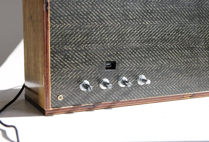
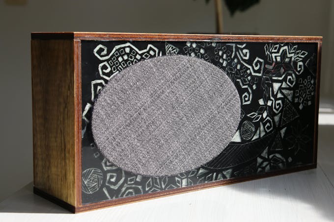
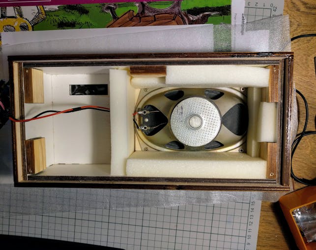
4. Enclosure

Use your fantasy.

Description:

Ard nano
Arduino Nano R3
×1
RDA5807M
×1
LM386
×1
MAX7219
×1
7 segment LED
×4

Description:

Description:

1. Goal

My goal was to make simple FM radio with a display that shows the frequency. And manual control over frequency and volume.

2. Hardware

You can use Arduino Uno or Nano:

2.1 RDA5807

The main component is RDA5807 Sinle-Chip FM Receiver Module. It's very tiny..So you need to build some kind adapter.

Connect RDA5807 pin 1 (SDA) to Arduino A4 and pin 2 (SCL) to Arduino A5. Pin 5 to 3.3v and pin 6 to Ground. Pin 10 is antenna. 7 is left and 8 is right audio output. The antenna may be just a piece of wire.

You can connect speaker directly to RDA5807:

Or connect to amplifier.

2.2 Amplifier

I used LM386 to make this simple mono audi amplifier:

2.3 Rotary Encoder

We use the Rotary Encoder to determine whether we are turning down (left) or up (right) the frequency.

2.4 7-Segment LED Display

It is easier and cheaper to buy readymade 7-segment LED module than to build it yourself.

But it is more fun to make it yourself. Like I did. There is many diffrent coloure and sizes 7-segment LEDs and they may be diffrent. So first test how it works. We need Common Cathode 7-segment LEDs. Mine looks like this:

I use MAX7219 IC to drive LEDs, but it does make a lot of electric noise. What can be heard from the speaker... Thay they that MAX7221 is better.

Connect MAX7219 DIN (Data In, leg 1) to Arduino D12, LOAD to D10 and CLK to D11.

3. Software

We use I2C protocol to communicate with RDA5807 Radio module:

#include <Wire.h>

Define Arduino pins what we use:

/* MAX7219 LED driver */
#define MAX7219_DIN 12
#define MAX7219_CS  10
#define MAX7219_CLK 11
/* Rotary Encoder */
#define clkPin 5 
#define dtPin  6 
#define swPin  2  

The code how to use RDA5807 I found it here: https://github.com/lucsmall/Arduino-RDA5807M

The channel is default frequensy what radio plays when it boot up.

If Radio frequensy is 106.1 MHz. (106.1 x 10) - 870 = 191

uint16_t channel = 191;

Address of the RDA5807 on two wire bus:

#define RDA5807M_ADDRESS  0b0010000 // 0x10

See the code here with all coments what it means: https://github.com/lucsmall/Arduino-RDA5807M/blob/master/A20150415RDA5807FMTuner.ino

#define BOOT_CONFIG_LEN 12
#define TUNE_CONFIG_LEN 4
uint8_t boot_config[] = {
 0b11000000,
 0b00000011,
 0b00000000, 
 0b00000000,
 0b00001010, 
 0b00000000, 
 0b10001000,  
 0b00001111, 
 0b00000000, 
 0b00000000, 
 0b01000010, 
 0b00000010,   
};
uint8_t tune_config[] = {
  0b11000000,  
  0b00000001, 
  (channel >> 2),  
  ((channel & 0b11) << 6 ) | 0b00010000
};

void setup()
{
 /* Rotary Encoder: */
 pinMode(clkPin, INPUT);
 pinMode(dtPin, INPUT);
 pinMode(swPin, INPUT); 
 digitalWrite(swPin, HIGH);
 /* Conect to RDA5807M FM Tuner: */
 Wire.begin(); /* join i2c bus (address optional for master) */
 Wire.beginTransmission(RDA5807M_ADDRESS); /* Sending boot configuration (device should reset) */
 Wire.write(boot_config, BOOT_CONFIG_LEN); /* Write the boot configuration bytes to the RDA5807M */
 Wire.endTransmission();
 Wire.beginTransmission(RDA5807M_ADDRESS); /* Tuning to channel */
 Wire.write(tune_config, TUNE_CONFIG_LEN); /* Write the tuning configuration bytes to the RDA5807M */
 Wire.endTransmission(); 
  // put your setup code here, to run once:
 initialise();
 output(0x0f, 0x00); //display test register - test mode off
 output(0x0c, 0x01); //shutdown register - normal operation
 output(0x0b, 0x07); //scan limit register - display digits 0 thru 7
 output(0x0a, 0x0f); //intensity register - max brightness
 output(0x09, 0xff); //decode mode register - CodeB decode all digits
 output(0x08, 0x0c); //digit 7 (leftmost digit) data
 output(0x07, 0x0b);
 output(0x06, 0x0d);
 output(0x05, 0x0e);
 output(0x04, 0x08);
 output(0x03, 0x07);
 output(0x02, 0x06);
 output(0x01, 0x05); //digit 0 (rightmost digit) data
}//setup end

Start main loop:

void loop()
{

Read Rotary Encoder:

 int change = getEncoderTurn();
 if (change > 0){
   channel++;
   myChangeChannel(channel);
   }
 else if(change < 0){
   channel--;
   myChangeChannel(channel);
   }

If you what to read Rotary Encoder Button:

 if(digitalRead(swPin) == LOW) //if button pull down
 {
   /* do something */
 }

We calculate every display digit separately:

 uint16_t frequency = channel+870;
 uint16_t num1 = (frequency / 1000) % 10;
 uint16_t num2 = (frequency / 100) % 10;
 uint16_t num3 = (frequency / 10) % 10;
 uint16_t num4 = frequency % 10;

Send digits to display:

 output(0x01, num1);
 output(0x02, num2);
 output(0x03, num3);
 output(0x04, num4);
}//loop end

Function to read Rotary Encoder turn: left or right. Returns: 1 or -1.

int getEncoderTurn(void)
{
 static int oldA = HIGH; // set the oldA as HIGH
 static int oldB = HIGH; // set the oldB as HIGH
 int result = 0;
 int newA = digitalRead(clkPin);   // read the value of clkPin to newA
 int newB = digitalRead(dtPin);    // read the value of dtPin to newB
 if (newA != oldA || newB != oldB) // if the value of clkPin or the dtPin has changed
 {
   /* something has changed */
   if (oldA == HIGH && newA == LOW)
   {
     result = (oldB * 2 - 1);
     /* Serial.print("Result: ");
        Serial.println(result); */
   }
 }
 oldA = newA;
 oldB = newB;
 return result; // 1 or -1
}

Function to change channel on radio RDA5807. Example: channel = 191

void myChangeChannel(int channel){ 
  //first write new channel to tune_config massive
  tune_config[2] = (channel >> 2); 
  tune_config[3] = ((channel & 0b11) << 6 ) | 0b00010000;
     Wire.begin();
     Wire.beginTransmission(RDA5807M_ADDRESS);
     Wire.write(tune_config, TUNE_CONFIG_LEN);
     Wire.endTransmission();
 }

Function to initialise MAX7219 7-segment LED display

void initialise()
{
 digitalWrite(MAX7219_CS, HIGH);
 pinMode(MAX7219_DIN, OUTPUT);
 pinMode(MAX7219_CS, OUTPUT);
 pinMode(MAX7219_CLK, OUTPUT);
}

Function to send data to MAX7219 7-segment LED display

void output(byte address, byte data)
{
 digitalWrite(MAX7219_CS, LOW);
 shiftOut(MAX7219_DIN, MAX7219_CLK, MSBFIRST, address);
 shiftOut(MAX7219_DIN, MAX7219_CLK, MSBFIRST, data);
 digitalWrite(MAX7219_CS, HIGH);
}

4. Enclosure

Use your fantasy.

Description:

RDA5807M_radio_max7219.inoArduino
Full code
/* 
 *
 *  Find RDA5807M code at: https://github.com/lucsmall/Arduino-RDA5807M
 *
 *  "Talking about my Arduino sketch for the RDA5807M FM Radio IC"
 *  http://youtu.be/9TegkAu96nE
 *
 *  "Connecting the RDA5807M FM Radio IC to an Arduino"
 *  https://youtu.be/2j1hX4uzkQ8
 *
 *  "Making my Arduino controlled RDA5807M FM Radio"
 *  https://youtu.be/4pZmkeqg5h8
 */

#include <Wire.h>

#define MAX7219_DIN 12
#define MAX7219_CS  10
#define MAX7219_CLK 11

/* Rotary Encoder: */
/*
const int clkPin = 5;   // clk - pin 5
const int dtPin  = 6;   //  dt - pin 6
const int swPin  = 2 ;  //  sw - pin 2
*/

#define clkPin 5   // clk - pin 5
#define dtPin  6   //  dt - pin 6
#define swPin  2  //  sw - pin 2


    /* Select the frequency we want to tune to by way
     * of selecting the channel for the desired frequency 
     */
uint16_t channel = 191; 
    /*
     * assuming band starts at 87.0MHz (per settings below)
     * and channel spacing of 100kHz (0.1MHz) (per settings below)
     * then channel can be derived as follows:
     *  
     * channel = (<desired freq in MHz> - 87.0) / 0.1 
     *
     * which is the same as:
     * <10 x desired freq in MHz> - 870
     *   
     *  some examples:
     * channel 145 dec = 101.5 MHz
     * channel 153 dec = 102.3 MHz
     * channel 177 dec = 104.7 MHz
     * channel 193 dec = 106.3 MHz
     * channel 209 dec = 107.9 MHz
     * 191 = 106.1 Vikerraadio
     * 187 = 105.7 Klassika raadio
     */

/* address of the RDA5807 on two wire bus */
#define RDA5807M_ADDRESS  0b0010000 // 0x10

#define BOOT_CONFIG_LEN 12
#define TUNE_CONFIG_LEN 4

/* 
 *  These bytes set our initial configuration
 *  We don't bother to tune to a channel at this stage.
 *  But instead initiate a reset.
 */
uint8_t boot_config[] = {
  /* register 0x02 */
  0b11000000,
    /* 
     * DHIZ audio output high-z disable
     * 1 = normal operation
     *
     * DMUTE mute disable 
     * 1 = normal operation
     *
     * MONO mono select
     * 0 = stereo
     *
     * BASS bass boost
     * 0 = disabled
     *
     * RCLK NON-CALIBRATE MODE 
     * 0 = RCLK is always supplied
     *
     * RCLK DIRECT INPUT MODE 
     * 0 = ??? not certain what this does
     *
     * SEEKUP
     * 0 = seek in down direction
     *
     * SEEK
     * 0 = disable / stop seek (i.e. don't seek)
     */
  0b00000011,
    /* 
     * SKMODE seek mode: 
     * 0 = wrap at upper or lower band limit and contiue seeking
     *
     * CLK_MODE clock mode
     *  000 = 32.768kHZ clock rate (match the watch cystal on the module) 
     *
     * RDS_EN radio data system enable
     * 0 = disable radio data system
     *
     * NEW_METHOD use new demodulate method for improved sensitivity
     * 0 = presumably disabled 
     *
     * SOFT_RESET
     * 1 = perform a reset
     *
     * ENABLE power up enable: 
     * 1 = enabled
     */ 

  /* register 0x03 */
    /* Don't bother to tune to a channel at this stage*/
  0b00000000, 
    /* 
     * CHAN channel select 8 most significant bits of 10 in total
     * 0000 0000 = don't boher to program a channel at this time
     */

  0b00000000,
    /* 
     * CHAN two least significant bits of 10 in total 
     * 00 = don't bother to program a channel at this time
     *
     * DIRECT MODE used only when test
     * 0 = presumably disabled
     *
     * TUNE commence tune operation 
     * 0 = disable (i.e. don't tune to selected channel)
     *
     * BAND band select
     * 00 = select the 87-108MHz band
     *
     * SPACE channel spacing
     * 00 = select spacing of 100kHz between channels
     */
     
  /* register 0x04 */
  0b00001010, 
    /* 
     * RESERVED 15
     * 0
     *
     * PRESUMABLY RESERVED 14
     * 0
     *
     * RESERVED 13:12
     * 00
     *
     * DE de-emphasis: 
     * 1 = 50us de-emphasis as used in Australia
     *
     * RESERVED
     * 0
     *
     * SOFTMUTE_EN
     * 1 = soft mute enabled
     *
     * AFCD AFC disable
     * 0 = AFC enabled
     */
  0b00000000, 
    /* 
     *  Bits 7-0 are not specified, so assume all 0's
     * 0000 0000
     */
  
  /* register 0x05 */
  0b10001000, 
    /* 
     * INT_MODE
     * 1 = interrupt last until read reg 0x0C
     *
     * RESERVED 14:12 
     * 000
     *
     * SEEKTH seek signal to noise ratio threshold
     * 1000 = suggested default
     */ 
  
  0b00001111, 
    /* 
     * PRESUMABLY RESERVED 7:6
     * 00
     *
     * RESERVED 5:4
     * 00
     *
     * VOLUME
     * 1111 = loudest volume
     */
  
  /* register 0x06 */
  0b00000000, 
    /* 
     * RESERVED 15
     * 0
     *
     * OPEN_MODE open reserved registers mode
     * 00 = suggested default
     *
     * Bits 12:8 are not specified, so assume all 0's
     * 00000
     */ 
   
  0b00000000, 
    /* 
     *  Bits 7:0 are not specified, so assume all 0's
     *  00000000
     */
    
  /* register 0x07 */
  0b01000010, 
    /* 
     *  RESERVED 15 
     * 0
     *
     * TH_SOFRBLEND threshhold for noise soft blend setting
     * 10000 = using default value
     *
     * 65M_50M MODE 
     * 1 = only applies to BAND setting of 0b11, so could probably use 0 here too
     *
     * RESERVED 8
     * 0
     */    
  
  0b00000010, 
    /*   
     *  SEEK_TH_OLD seek threshold for old seek mode
     * 000000
     *
     * SOFTBLEND_EN soft blend enable
     * 1 = using default value
     *
     * FREQ_MODE
     * 0 = using defualt value
     */  
};

/* After reset, we can tune the device
 * We only need program the first 4 bytes in order to do this
 */
uint8_t tune_config[] = {
  /* register 0x02 */
  0b11000000, 
    /* 
     * DHIZ audio output high-z disable
     * 1 = normal operation
     *
     * DMUTE mute disable 
     * 1 = normal operation
     *
     * MONO mono select
     * 0 = stereo
     *
     * BASS bass boost
     * 0 = disabled
     *
     * RCLK NON-CALIBRATE MODE 
     * 0 = RCLK is always supplied
     *
     * RCLK DIRECT INPUT MODE 
     * 0 = ??? not certain what this does
     *
     * SEEKUP
     * 0 = seek in down direction
     *
     * SEEK
     * 0 = disable / stop seek (i.e. don't seek)
     */
    
   0b00000001, 
    /* 
     * SKMODE seek mode: 
     * 0 = wrap at upper or lower band limit and contiue seeking
     *
     * CLK_MODE clock mode
     * 000 = 32.768kHZ clock rate (match the watch cystal on the module) 
     *
     * RDS_EN radio data system enable
     * 0 = disable radio data system
     *
     * NEW_METHOD use new demodulate method for improved sensitivity
     * 0 = presumably disabled 
     *
     * SOFT_RESET
     * 0 = don't reset this time around
     *
     * ENABLE power up enable: 
     * 1 = enabled
     */ 

   /* register 0x03 */
   /* Here's where we set the frequency we want to tune to */
   (channel >> 2), 
    /* CHAN channel select 8 most significant bits of 10 in total   */

   ((channel & 0b11) << 6 ) | 0b00010000
    /* 
     *  CHAN two least significant bits of 10 in total 
     *
     * DIRECT MODE used only when test
     * 0 = presumably disabled
     *
     * TUNE commence tune operation 
     * 1 = enable (i.e. tune to selected channel)
     *
     * BAND band select
     * 00 = select the 87-108MHz band
     *
     * SPACE channel spacing
     * 00 = select spacing of 100kHz between channels
     */  
};


void setup()
{
  Serial.begin(9600);
  
  /* Rotary Encoder: */
  pinMode(clkPin, INPUT);
  pinMode(dtPin, INPUT);
  pinMode(swPin, INPUT); 
  digitalWrite(swPin, HIGH);

  
  /* Conect to RDA5807M FM Tuner: */
  Wire.begin(); /* join i2c bus (address optional for master) */
  
  Wire.beginTransmission(RDA5807M_ADDRESS); /* Sending boot configuration (device should reset) */
  Wire.write(boot_config, BOOT_CONFIG_LEN); /* Write the boot configuration bytes to the RDA5807M */
  Wire.endTransmission();
  
  Wire.beginTransmission(RDA5807M_ADDRESS); /* Tuning to channel */
  Wire.write(tune_config, TUNE_CONFIG_LEN); /* Write the tuning configuration bytes to the RDA5807M */
  Wire.endTransmission(); 


   // put your setup code here, to run once:
   
  initialise();
  output(0x0f, 0x00); //display test register - test mode off
  output(0x0c, 0x01); //shutdown register - normal operation
  output(0x0b, 0x07); //scan limit register - display digits 0 thru 7
  output(0x0a, 0x0f); //intensity register - max brightness
  output(0x09, 0xff); //decode mode register - CodeB decode all digits
  output(0x08, 0x0c); //digit 7 (leftmost digit) data
  output(0x07, 0x0b);
  output(0x06, 0x0d);
  output(0x05, 0x0e);
  output(0x04, 0x08);
  output(0x03, 0x07);
  output(0x02, 0x06);
  output(0x01, 0x05); //digit 0 (rightmost digit) data
  
  
}//setup end

void loop()
{
  /* Read Rotary Encoder: */
  int change = getEncoderTurn();

  if (change > 0){
    channel++;
    myChangeChannel(channel);
    }
  else if(change < 0){
    channel--;
    myChangeChannel(channel);
    }

  /* Rotary Encoder Button: */
  if(digitalRead(swPin) == LOW) //if button pull down
  {
    /* tee midagi kui nuppu vajutatud 
       salvesta niteks sagedus mllu!
       */
  }

  uint16_t frequency = channel+870;

  uint16_t num1 = (frequency / 1000) % 10;
  uint16_t num2 = (frequency / 100) % 10;
  uint16_t num3 = (frequency / 10) % 10;
  uint16_t num4 = frequency % 10;

  Serial.print(num1);
  Serial.print(num2);
  Serial.print(num3);
  Serial.print(num4);
  Serial.print("--");
  Serial.println(channel+870);
  

  // put your main code here, to run repeatedly: 
  
  output(0x01, num1);
  output(0x02, num2);
  output(0x03, num3);
  output(0x04, num4);
  
  
  //delay(100);
  
}//loop end

/*
 * Function to read Rotary Encoder turn:
 * left or right
 * Returns: 1 or -1
 */
int getEncoderTurn(void)
{
  static int oldA = HIGH; // set the oldA as HIGH
  static int oldB = HIGH; // set the oldB as HIGH
  int result = 0;
  int newA = digitalRead(clkPin);   // read the value of clkPin to newA
  int newB = digitalRead(dtPin);    // read the value of dtPin to newB
  
  if (newA != oldA || newB != oldB) // if the value of clkPin or the dtPin has changed
  {
    /* something has changed */
    if (oldA == HIGH && newA == LOW)
    {
      result = (oldB * 2 - 1);
      /* Serial.print("Result: ");
         Serial.println(result); */
    }
  }
  oldA = newA;
  oldB = newB;
  
  return result; // 1 or -1
}


/*
 * Function to change channel on radio RDA5807
 * Example: channel = 191 
 */
void myChangeChannel(int channel){ /* void if nothing is returned else int */
  /*
   * first write new channel to tune_config massive
   */
   tune_config[2] = (channel >> 2); 
   tune_config[3] = ((channel & 0b11) << 6 ) | 0b00010000;
      
      Wire.begin();
      Wire.beginTransmission(RDA5807M_ADDRESS);
      Wire.write(tune_config, TUNE_CONFIG_LEN);
      Wire.endTransmission();
  }

/*
 * Function to initialise MAX7219 7-segment LED display
 */
void initialise()
{
  digitalWrite(MAX7219_CS, HIGH);
  pinMode(MAX7219_DIN, OUTPUT);
  pinMode(MAX7219_CS, OUTPUT);
  pinMode(MAX7219_CLK, OUTPUT);
}

/*
 * Function to send data to MAX7219 7-segment LED display
 */
void output(byte address, byte data)
{
  digitalWrite(MAX7219_CS, LOW);
  shiftOut(MAX7219_DIN, MAX7219_CLK, MSBFIRST, address);
  shiftOut(MAX7219_DIN, MAX7219_CLK, MSBFIRST, data);
  digitalWrite(MAX7219_CS, HIGH);
}


YOU MIGHT ALSO LIKE