Frequency Counter for Android
DESCRIPTION
The Android app is made using MIT App Inventor which is an easy way to make Android apps. http://appinventor.mit.edu/explore/ . The app has buttons to connect and disconnect the Bluetooth to the phone and 2 displays of voltage and frequency. The .apk file is the file that installs manually the app to your phone. The .aia file can be imported after you install the MIT App Inventor. The software (1.5 MB) can be downloaded from github.
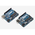
The Arduino generates an accurate 1 second time base for the counter by cascading timer0 and timer2. The link between digital inputs 3 and 4 connects the output of timer2, 250 Hz, to input of timer0. The software waits for the output of timer0 to go positive to start the count of frequency input to timer1. Timer1 is a 16 bits timer, it overflows at the count of 32768, that in turn advances overFlow register. At the end of the 1 second the 16 bit register is recorded. The Arduino then sends to the Bluetooth 5 bytes of data in serial RS232 protocol.
The Bluetooth module HC-05 can be paired with the phone using the code 1234.
The frequency input is TTL signal levels, for low signal a video amp has to be added. The specs recommend input up to 6 MHz, I tested it at 2 MHz. The voltage input is 0-5VDC.


