Home Automation Using ESP8266 Wi-Fi Module Without Internet
DESCRIPTION
hello friends, in this tutorial, we are going to make a home automation using espmodule without internet.
I hope lot of peoples used and heard about the home automation using bluetooth. as same like that, we are going to make a home automation using ESP8266 instead o bluetooth.
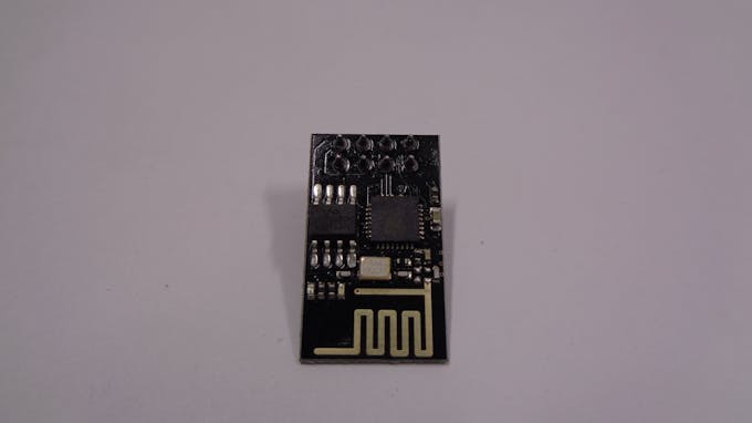
Step 1: Make a Esp Breakout Board of Your Own
I strongly recommend to buy a breakout board from the online market. that is quiet convenient for you. connect the TX to RX of the arduino pin. connect RX to the TX of the arduino pin
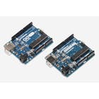
Step 2: Connect the Relay Module to A0, A1, A2, A3 of the Arduino Board
You can also use any digital pins from the arduino and make the suitable changes in the arduino code.
connect the ESP module to arduino as I said in the previous step
Step 3: Download the Code Which I Given in the Attachment.
make a suitable changes in the code like the WIFI name, password. then download the code. before download the code, make sure that you have removed the tx and rx pin from the esp to the arduino board. after downloading the program, reconnect it.
Step 4: Open Your Playstore and Download the Socket Control Widget and Install It
https://play.google.com/store/apps/details?id=com.froelix.homeautomation.socketcontrolwidget&hl=en
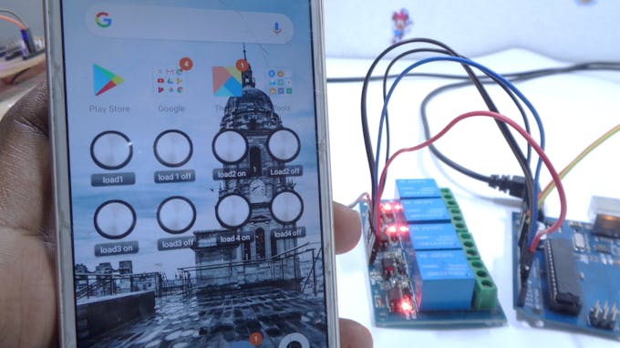
Step 5: Go to the Widgets From Your Mobile and Place Socket Widget in the Home Screen and Change the Settings Given Below
Place the Widget in the home screen.
open the widget
give a name as light ON and corresponding for 8 widget buttons as we need. (dont confused it, watch the video)
type the following line below command
192.168.4.1:80/ FA
for next widget button for light OFF
192.168.4.1:80/FB
similarly.. FC to FH you have to create
Step 6: Enable the WIFI on the Mobile, Scan the ESP Module and Connect It
Connect the esp module through wifi
give stay connect if the warning appear.
if it asked password, give your password given on the arduino code. then go to home menu
Step 7: Touch the Widget After Successful Connection, the Relay Will Be Switched ON/OFF
that the end. enjoy with the tech.
| × | 1 | ||||
 |
| × | 1 | |||
| × | 1 | ||||
| × | 1 |
hello friends, in this tutorial, we are going to make a home automation using espmodule without internet.
I hope lot of peoples used and heard about the home automation using bluetooth. as same like that, we are going to make a home automation using ESP8266 instead o bluetooth.
Step 1: Make a Esp Breakout Board of Your Own
I strongly recommend to buy a breakout board from the online market. that is quiet convenient for you. connect the TX to RX of the arduino pin. connect RX to the TX of the arduino pin
Step 2: Connect the Relay Module to A0, A1, A2, A3 of the Arduino Board
You can also use any digital pins from the arduino and make the suitable changes in the arduino code.
connect the ESP module to arduino as I said in the previous step
Step 3: Download the Code Which I Given in the Attachment.
make a suitable changes in the code like the WIFI name, password. then download the code. before download the code, make sure that you have removed the tx and rx pin from the esp to the arduino board. after downloading the program, reconnect it.
Step 4: Open Your Playstore and Download the Socket Control Widget and Install It
https://play.google.com/store/apps/details?id=com.froelix.homeautomation.socketcontrolwidget&hl=en
Step 5: Go to the Widgets From Your Mobile and Place Socket Widget in the Home Screen and Change the Settings Given Below
Place the Widget in the home screen.
open the widget
give a name as light ON and corresponding for 8 widget buttons as we need. (dont confused it, watch the video)
type the following line below command
192.168.4.1:80/ FA
for next widget button for light OFF
192.168.4.1:80/FB
similarly.. FC to FH you have to create
Step 6: Enable the WIFI on the Mobile, Scan the ESP Module and Connect It
Connect the esp module through wifi
give stay connect if the warning appear.
if it asked password, give your password given on the arduino code. then go to home menu
Step 7: Touch the Widget After Successful Connection, the Relay Will Be Switched ON/OFF
that the end. enjoy with the tech.


