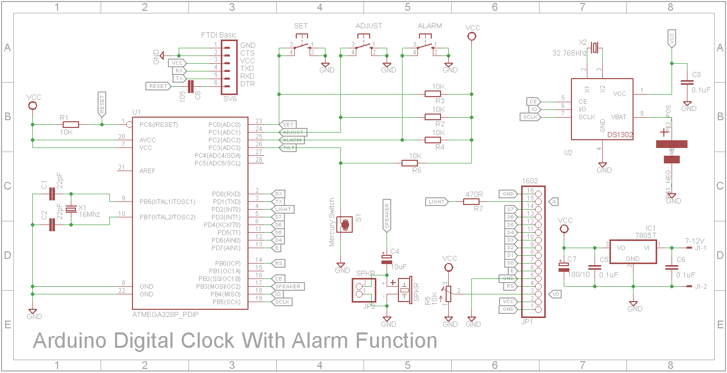
/*  1602 LCD alarm clock
 *  by John Bradnam ([email protected])
 *
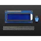
 *  Display 16x2:         Setup:            Setup Alarm
 *  +----------------+  +----------------+ +----------------+
 *  |HH:MM:SS | HH:MM|  |    >HH :>MM    | |   Set Alarm    |
 *  |DD/MM/YY | ALARM|  |>DD />MM />YYYY | |   >HH :>MM     |
 *  +----------------+  +----------------+ +----------------+
 *
 *  25/06/2020
 *    - Took Michalis Vasilakis's clock as code base (https://www.instructables.com/id/Arduino-Digital-Clock-With-Alarm-Function-custom-P/)
 *    - Modified to suit hardware - DS1302 RTC and LCD backlight
 *    - Added support for different display styles
 *      - Standard screen design by Michalis Vasilakis
 *      - Dual Thick font by Arduino World (https://www.hackster.io/thearduinoworld/arduino-digital-clock-version-1-b1a328)
 *      - Dual Bevelled font by Arduino Forum (https://forum.arduino.cc/index.php/topic,8882.0.html)
 *      - Dual Trek font by Carrie Sundra (https://www.alpenglowindustries.com/blog/the-big-numbers-go-marching-2x2)
 *      - Dual Thin font by Arduino World (https://www.hackster.io/thearduinoworld/arduino-digital-clock-version-2-5bab65)
 *      - Word concept by LAGSILVA (https://www.hackster.io/lagsilva/text-clock-bilingual-en-pt-with-arduino-881a6e)
 *  29/06/20
 *    - Fixed spelling mistakes in WORD clock
 *    - Added #defines to control backlight
 *    - Increased backlight timeout from 5 to 10 seconds
 */

//Libraries
#include <Wire.h>
#include <TimeLib.h>
#include <DS1302RTC.h>
#include <LiquidCrystal.h>
#include <EEPROM.h>

//uncomment if you want the dual thick or thin display variant to show 12hr format
//#define DUAL_THICK_12HR
//#define DUAL_THIN_12HR

//uncomment to control backlight
//#define NO_BACKLIGHT
//#define BACKLIGHT_ALWAYS_ON
#define BACKLIGHT_TIMEOUT 10000

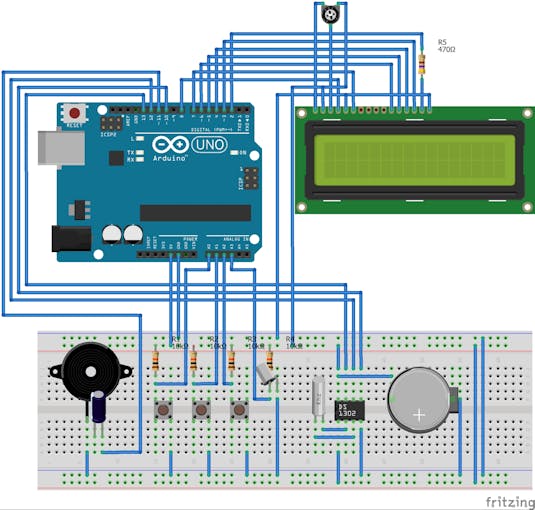
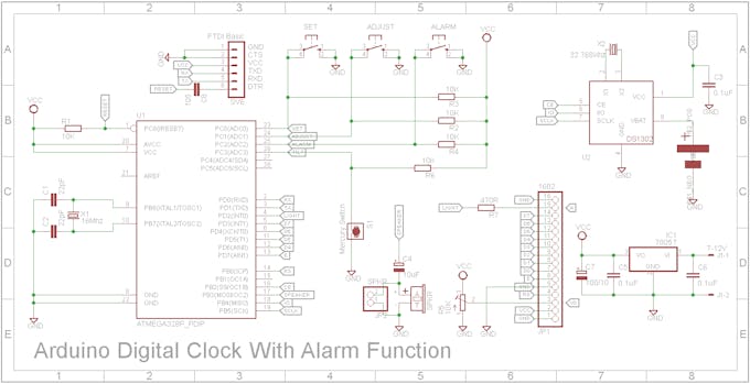
#define LIGHT           2  //PD2
#define LCD_D7          3  //PD3
#define LCD_D6          4  //PD4
#define LCD_D5          5  //PD5
#define LCD_D4          6  //PD6
#define LCD_E           7  //PD7
#define LCD_RS          8  //PB0
#define BTN_SET         A0 //PC0
#define BTN_ADJUST      A1 //PC1
#define BTN_ALARM       A2 //PC2
#define BTN_TILT        A3 //PC3
#define SPEAKER         11 //PB3
#define RTC_CE          10 //PB2
#define RTC_IO          12 //PB4
#define RTC_SCLK        13 //PB5


//Connections and constants
LiquidCrystal lcd(LCD_RS, LCD_E, LCD_D4, LCD_D5, LCD_D6, LCD_D7);
DS1302RTC rtc(RTC_CE, RTC_IO, RTC_SCLK);

//RTC_DS1307 rtc; //DS1307 i2c
char daysOfTheWeek[7][12] = {"Sunday","Monday", "Tuesday", "Wednesday", "Thursday", "Friday", "Saturday"};
long interval = 300;
int melody[] = { 600, 800, 1000,1200 };

//Variables
int DD,MM,YY,H,M,S,set_state, adjust_state, alarm_state,AH,AM, shake_state;
int shakeTimes=0;
int i =0;
int btnCount = 0;
String sDD;
String sMM;
String sYY;
String sH;
String sM;
String sS;
String aH="12";
String aM="00";
String alarm = "     ";
long previousMillis = 0;

//Boolean flags
boolean setupScreen = false;
boolean alarmON=false;
boolean turnItOn = false;

enum STYLE { STANDARD, DUAL_THICK, DUAL_BEVEL, DUAL_TREK, DUAL_THIN, WORD };
STYLE currentStyle = STANDARD;

bool backlightOn = false;
long backlightTimeout = 0;

byte customChar[8];

//--------------------- Word clock --------------------------------------
String units[] = {"HUNDRED", "ONE", "TWO", "THREE", "FOUR", "FIVE", "SIX", "SEVEN", "EIGHT", "NINE"};
String teens[] = {"TEN", "ELEVEN", "TWELVE", "THIRTEEN", "FOURTEEN", "FIFTEEN", "SIXTEEN", "SEVENTEEN", "EIGHTEEN", "NINETEEN"};
String tens[] = {"", "", "TWENTY", "THIRTY", "FORTY", "FIFTY"};

//---------------------- Hourglass animation ----------------------------
#define HOURGLASS_FRAMES 8
#define HOURGLASS_CHAR 0
#define FRAME_TIMEOUT 200;
int nextFrame = 0;
long frameTimeout = 0;
const byte hourglass[HOURGLASS_FRAMES][8] PROGMEM = {
  { B11111,  B11111,  B01010,  B01010,  B01010,  B01010,  B10001,  B11111 },
  { B11111,  B11011,  B01110,  B01010,  B01010,  B01010,  B10001,  B11111 },
  { B11111,  B10001,  B01110,  B01110,  B01010,  B01010,  B10001,  B11111 },
  { B11111,  B10001,  B01010,  B01110,  B01110,  B01010,  B10001,  B11111 },
  { B11111,  B10001,  B01010,  B01010,  B01110,  B01110,  B10001,  B11111 },
  { B11111,  B10001,  B01010,  B01010,  B01010,  B01110,  B10101,  B11111 },
  { B11111,  B10001,  B01010,  B01010,  B01010,  B01110,  B11011,  B11111 },
  { B11111,  B10001,  B01010,  B01010,  B01010,  B01010,  B11111,  B11111 },
  //{ B11111,  B10001,  B01010,  B01010,  B01010,  B01010,  B10001,  B11111 }
};

//---------------------- Alarm and clock custom characters ----------------------------
#define BELL_CHAR 1
#define CLOCK_CHAR 2
const byte bell[8] PROGMEM  = {0x4, 0xe, 0xe, 0xe, 0x1f, 0x0, 0x4};
const byte clock[8] PROGMEM = {0x0,0xe,0x15,0x17,0x11,0xe,0x0};

//---------------------- Thick Square Font ----------------------------
#define C0 3
#define C1 4
#define C2 5
#define C3 6
const byte C_0[8] PROGMEM = {0x1F,0x1F,0x1F,0x00,0x00,0x00,0x00,0x00};
const byte C_1[8] PROGMEM = {0x1F,0x1F,0x1F,0x00,0x00,0x1F,0x1F,0x1F};
const byte C_2[8] PROGMEM = {0x00,0x00,0x00,0x00,0x00,0x1F,0x1F,0x1F};
const byte C_3[8] PROGMEM = {0x00,0x00,0x0E,0x0A,0x0A,0x0E,0x00,0x00};

const byte blockChar[11][2][3] = {
  {{ 255, C0, 255}, {255, C2, 255}}, //0
  {{ C0, 255, 32}, {C2, 255, C2}}, //1
  {{ C0, C0, 255}, {255, C1, C2}}, //2
  {{ C1, C1, 255}, {C1, C1, 255}}, //3
  {{ 255, C2, 255}, {32, 32, 255}}, //4
  {{ 255, C1, C1}, {C2, C2, 255}}, //5
  {{ 255, C0, C0}, {255, C1, 255}}, //6
  {{ C0, C1, 255}, {32, C0, 255}}, //7
  {{ 255, C1, 255}, {255, C1, 255}}, //8
  {{ 255, C1, 255}, {C2, C2, 255}}, //9
  {{ 32, 32, 32}, {32, 32, 32}}, //Blank
};

//---------------------- Thick Bevel Font ----------------------------
#define LT 0
#define UB 1
#define RT 2
#define LL 3
#define LB 4
#define LR 5
#define UMB 6
#define LMB 7

const byte _LT[8] PROGMEM = { B00111, B01111, B11111, B11111, B11111, B11111, B11111, B11111};
const byte _UB[8] PROGMEM = { B11111, B11111, B11111, B00000, B00000, B00000, B00000, B00000};
const byte _RT[8] PROGMEM = { B11100, B11110, B11111, B11111, B11111, B11111, B11111, B11111};
const byte _LL[8] PROGMEM = { B11111, B11111, B11111, B11111, B11111, B11111, B01111, B00111};
const byte _LB[8] PROGMEM = { B00000, B00000, B00000, B00000, B00000, B11111, B11111, B11111};
const byte _LR[8] PROGMEM = { B11111, B11111, B11111, B11111, B11111, B11111, B11110, B11100};
const byte _UMB[8] PROGMEM = { B11111, B11111, B11111, B00000, B00000, B00000, B11111, B11111};
const byte _LMB[8] PROGMEM = { B11111, B11111, B11111, B11111, B11111, B11111, B11111, B11111};

const byte bevelChar[11][2][3] = {
  {{LT, UB, RT}, {LL, LB, LR}}, //0
  {{UB, RT, 32}, {LB, LMB, LB}}, //1
  {{UMB, UMB, RT}, {LL, LB, LB}}, //2
  {{UMB, UMB, RT}, {LB, LB, LR}}, //3
  {{LL, LB, LMB}, {32, 32, LMB}}, //4
  {{LT, UMB, UMB}, {LB, LB, LR}}, //5
  {{LT, UMB, UMB}, {LL, LB, LR}}, //6
  {{UB, UB, RT}, {32, 32, LT}}, //7
  {{LT, UMB, RT}, {LL, LB, LR}}, //8
  {{LT, UMB, RT}, {32, 32, LR}}, //9
  {{ 32, 32, 32}, {32, 32, 32}} //Blank
};

//---------------------- Trek Font ----------------------------
#define K0 0
#define K1 1
#define K2 2
#define K3 3
#define K4 4
#define K5 5
#define K6 6
#define K7 7
const byte K_0[8] PROGMEM = {0x1F,0x1F,0x00,0x00,0x00,0x00,0x00,0x00};
const byte K_1[8] PROGMEM = {0x18,0x18,0x18,0x18,0x18,0x18,0x18,0x18};
const byte K_2[8] PROGMEM = {0x00,0x00,0x00,0x00,0x00,0x00,0x1F,0x1F};
const byte K_3[8] PROGMEM = {0x1F,0x1F,0x03,0x03,0x03,0x03,0x1F,0x1F};
const byte K_4[8] PROGMEM = {0x1F,0x1F,0x18,0x18,0x18,0x18,0x1F,0x1F};
const byte K_5[8] PROGMEM = {0x1F,0x1F,0x18,0x18,0x18,0x18,0x18,0x18};
const byte K_6[8] PROGMEM = {0x03,0x03,0x03,0x03,0x03,0x03,0x1F,0x1F};
const byte K_7[8] PROGMEM = {0x1F,0x1F,0x03,0x03,0x03,0x03,0x03,0x03};

const byte trekChar[11][2][2] = {
  {{ K5, K7}, {255, K6}}, //0
  {{ K0, K1}, {K2, 255}}, //1
  {{ K0, K3}, {255, K2}}, //2
  {{ K0, K3}, {K2, 255}}, //3
  {{ K1, 255}, {K0, K1}}, //4
  {{ K4, K0}, {K2, 255}}, //5
  {{ K5, K0}, {K4, 255}}, //6
  {{ K0, 255}, {32, K1}}, //7
  {{ 255, K3}, {K4, 255}}, //8
  {{ 255, K3}, {K2, K6}}, //9
  {{ 32, 32}, {32, 32}}, //Blank
};


//---------------------- Thin Font ----------------------------
#define T0 0
#define T1 1
#define T2 2
#define T3 3
#define T4 4
#define T5 5
#define T6 6
#define T7 7

const byte T_0[8] PROGMEM = {0x02,0x02,0x02,0x02,0x02,0x02,0x02,0x02};
const byte T_1[8] PROGMEM = {0x0E,0x02,0x02,0x02,0x02,0x02,0x02,0x0E};
const byte T_2[8] PROGMEM = {0x0E,0x08,0x08,0x08,0x08,0x08,0x08,0x0E};
const byte T_3[8] PROGMEM = {0x0E,0x0A,0x0A,0x0A,0x0A,0x0A,0x0A,0x0E};
const byte T_5[8] PROGMEM = {0x0A,0x0A,0x0A,0x0A,0x0A,0x0A,0x0A,0x0E};
const byte T_4[8] PROGMEM = {0x0E,0x0A,0x0A,0x0A,0x0A,0x0A,0x0A,0x0A};
const byte T_6[8] PROGMEM = {0x0E,0x02,0x02,0x02,0x02,0x02,0x02,0x02};
const byte T_7[8] PROGMEM = {0x18,0x18,0x18,0x18,0x18,0x1E,0x1F,0x1F};

//lcd draw character functions
const byte thinChar[11][2] = {
  {T4, T5}, //0
  {T0, T0}, //1
  {T1, T2}, //2
  {T1, T1}, //3
  {T5, T6}, //4
  {T2, T1}, //5
  {T2, T3}, //6
  {T6, T0}, //7
  {T3, T3}, //8
  {T3, T1}, //9
  {32, 32}  //blank
};

//---------------------- General initialisation ----------------------------
void setup()
{
  Serial.begin(115200);

  //Set outputs/inputs
  pinMode(BTN_SET,INPUT);
  pinMode(BTN_ADJUST,INPUT);
  pinMode(BTN_ALARM, INPUT);
  pinMode(BTN_TILT, INPUT);
  pinMode(SPEAKER, OUTPUT);
  pinMode(LIGHT, OUTPUT);

  //Check if RTC has a valid time/date, if not set it to 00:00:00 01/01/2018.
  //This will run only at first time or if the coin battery is low.

  //setSyncProvider() causes the Time library to synchronize with the
  //external RTC by calling RTC.get() every five minutes by default.
  setSyncProvider(rtc.get);
  if (timeStatus() != timeSet)
  {
    Serial.println("Setting default time");
    //Set RTC
    tmElements_t tm;
    tm.Year = CalendarYrToTm(2020);
    tm.Month = 06;
    tm.Day = 26;
    tm.Hour = 7;
    tm.Minute = 52;
    tm.Second = 0;
    time_t t = makeTime(tm);
    //use the time_t value to ensure correct weekday is set
    if (rtc.set(t) == 0)
    { // Success
      setTime(t);
    }
    else
    {
      Serial.println("RTC set failed!");
    }
  }

  delay(100);
  //Read alarm time from EEPROM memmory
  AH = EEPROM.read(0);
  AM = EEPROM.read(1);
  byte ao = EEPROM.read(2);
  alarmON = (ao != 0);
  byte cs = EEPROM.read(3);
  //Check if the numbers that you read are valid. (Hours:0-23 and Minutes: 0-59)
  if (AH > 23)
  {
    AH = 0;
  }
  if (AM > 59){
    AM = 0;
  }
  //Setup current style
  lcd.begin(16,2);
  currentStyle = (cs > (uint8_t)WORD) ? STANDARD : (STYLE)cs;
  switch (currentStyle)
  {
    case STANDARD: lcdStandardSetup(); break;
    case DUAL_THICK: lcdDualThickSetup(); break;
    case DUAL_BEVEL: lcdDualBevelSetup(); break;
    case DUAL_TREK: lcdDualTrekSetup(); break;
    case DUAL_THIN: lcdDualThinSetup(); break;
    case WORD:     lcdWordSetup(); break;
  }
}

//---------------------- Main program loop ----------------------------
void loop()
{
  readBtns();       //Read buttons
  getTimeDate();    //Read time and date from RTC
  if (!setupScreen)
  {
    lcdPrint();     //Normanlly print the current time/date/alarm to the LCD
    if (alarmON)
    {
      callAlarm();  // and check the alarm if set on
      if (turnItOn)
      {
        switchBacklight(true);
      }
    }
    //Serial.println("backlightTimeout=" + String(backlightTimeout) + ", millis()=" + String(millis()) + ", backlightOn=" + String(backlightOn));
    if (backlightOn && (millis() > backlightTimeout))
    {
      switchBacklight(false);
    }
  }
  else
  {
    timeSetup();    //If button set is pressed then call the time setup function
    switchBacklight(true);
  }
}

//--------------------------------------------------
//Read buttons state
void readBtns()
{
  set_state = digitalRead(BTN_SET);
  adjust_state = digitalRead(BTN_ADJUST);
  alarm_state = digitalRead(BTN_ALARM);
  if (!backlightOn && !setupScreen)
  {
    if (set_state == LOW || adjust_state == LOW || alarm_state == LOW)
    {
      //Turn on backlight
      switchBacklight(true);
      //need to hold down button for at least 1/2 a second
      delay(500);
    }
  }
  else
  {
    if(!setupScreen)
    {
      if (alarm_state == LOW)
      {
        alarmON = !alarmON;
        EEPROM.write(2, (alarmON) ? 1 : 0);
        delay(500);
        switchBacklight(true);
      }
      else if (adjust_state == LOW)
      {
        currentStyle = (currentStyle == WORD) ? STANDARD : (STYLE)((int)currentStyle + 1);
        EEPROM.write(3, (byte)currentStyle);
        switch (currentStyle)
        {
          case STANDARD: lcdStandardSetup(); break;
          case DUAL_THICK: lcdDualThickSetup(); break;
          case DUAL_BEVEL: lcdDualBevelSetup(); break;
          case DUAL_TREK: lcdDualTrekSetup(); break;
          case DUAL_THIN: lcdDualThinSetup(); break;
          case WORD:     lcdWordSetup(); break;
        }
        lcd.clear();
        lcdPrint();
        delay(500);
        switchBacklight(true);
      }
    }

    if (set_state == LOW)
    {
      if( btnCount < 7 )
      {
        btnCount++;
        setupScreen = true;
        if (btnCount == 1)
        {
          lcd.clear();
          lcd.setCursor(0,0);
          lcd.print("------SET------");
          lcd.setCursor(0,1);
          lcd.print("-TIME and DATE-");
          delay(2000);
          lcd.clear();
        }
      }
      else
      {
        lcd.clear();
        //Set RTC
        tmElements_t tm;
        tm.Year = CalendarYrToTm(YY);
        tm.Month = MM;
        tm.Day = DD;
        tm.Hour = H;
        tm.Minute = M;
        tm.Second = 0;
        time_t t = makeTime(tm);
        //use the time_t value to ensure correct weekday is set
        if (rtc.set(t) == 0)
        { // Success
          setTime(t);
        }
        else
        {
          Serial.println("RTC set failed!");
        }
        //rtc.adjust(DateTime(YY, MM, DD, H, M, 0)); //Save time and date to RTC IC

        EEPROM.write(0, AH);  //Save the alarm hours to EEPROM 0
        EEPROM.write(1, AM);  //Save the alarm minuted to EEPROM 1

        lcd.print("Saving....");
        delay(2000);
        lcd.clear();
        setupScreen = false;
        btnCount=0;
        switchBacklight(true);
      }
      delay(500);
    }
  }
}

//--------------------------------------------------
//Read time and date from rtc ic
void getTimeDate()
{
  if (!setupScreen)
  {
    //DateTime now = rtc.now();
    time_t t = now();
    DD = day(t);
    MM = month(t);
    YY = year(t);
    H = hour(t);
    M = minute(t);
    S = second(t);
  }
  //Make some fixes...
  sDD = ((DD < 10) ? "0" : "") + String(DD);
  sMM = ((MM < 10) ? "0" : "") + String(MM);
  sYY = String(YY-2000);
  sH = ((H < 10) ? "0" : "") + String(H);
  sM = ((M < 10) ? "0" : "") + String(M);
  sS = ((S < 10) ? "0" : "") + String(S);
  aH = ((AH < 10) ? "0" : "") + String(AH);
  aM = ((AM < 10) ? "0" : "") + String(AM);
}

//--------------------------------------------------
//Switch on or off backlight
void switchBacklight(bool on)
{
  #ifdef NO_BACKLIGHT
    digitalWrite(LIGHT, LOW);
    backlightOn = true;  //Fool software into thinking its on even though it isn't
  #else
    #ifdef BACKLIGHT_ALWAYS_ON
      digitalWrite(LIGHT, HIGH);
      backlightOn = true;
    #else
      digitalWrite(LIGHT, (on) ? HIGH : LOW);
      backlightOn = on;
    #endif
  #endif
  backlightTimeout = millis() + BACKLIGHT_TIMEOUT;
}

//--------------------------------------------------
//Print values to the display
void lcdPrint()
{
  switch (currentStyle)
  {
    case STANDARD: lcdStandardLayout(); break;
    case DUAL_THICK: lcdDualThickLayout(); break;
    case DUAL_BEVEL: lcdDualBevelLayout(); break;
    case DUAL_TREK: lcdDualTrekLayout(); break;
    case DUAL_THIN: lcdDualThinLayout(); break;
    case WORD:     lcdWordLayout(); break;
  }
}

//------------------------------------------------ Standard layout ---------------------------------------------------------------------
void lcdStandardSetup()
{
}

void lcdStandardLayout()
{
  String line1 = sH+":"+sM+":"+sS+" | "+aH+":"+aM;
  String line2 = sDD+"/"+sMM+"/"+sYY +" | " + ((alarmON && (S & 0x01)) ? "ALARM" : "     ");
;
  lcd.setCursor(0,0); //First row
  lcd.print(line1);
  lcd.setCursor(0,1); //Second row
  lcd.print(line2);
}

//Create a custom character from program memory
void createCharP(byte slot, byte* p)
{

  for (int i = 0; i < 8; i++)
  {
    customChar[i] = pgm_read_byte(p++);
  }
  lcd.createChar(slot, customChar);
}

//------------------------------------------------ Dual Thick layout ---------------------------------------------------------------------
void lcdDualThickSetup()
{
  createCharP(C0, C_0);
  createCharP(C1, C_1);
  createCharP(C2, C_2);
  createCharP(C3, C_3);

  createCharP(BELL_CHAR, bell);
}

void lcdDualThickLayout()
{

#ifdef DUAL_THICK_12HR

  int h = (H >= 12) ? H - 12 : H;
  if (h == 0)
  {
    h = 12;
  }
  lcdDualThickPrintNumber(8, M, true);
  lcdDualThickPrintNumber(0, h, false);

  lcd.setCursor(15,0);
  lcd.print((H >= 12) ? "p" : "a");
  lcd.setCursor(15,1);
  lcd.print("m");

#else

  lcdDualThickPrintNumber(8, M, true);
  lcdDualThickPrintNumber(0, H, true);

  bool alarm = (S & 0x01);
  lcdWordShowBell(15, 0, alarm, BELL_CHAR); //bottonm right corner
  lcdWordShowBell(15, 1, !alarm, BELL_CHAR); //bottonm right corner

#endif

  byte c = (S & 1) ? C3 : 32;
  lcd.setCursor(7,0);
  lcd.write(c);
  lcd.setCursor(7,1);
  lcd.write(c);
}

//Draw a 2 line number
// pos - x position to draw number
// number - value to draw
// leadingZero - whether leading zeros should be displayed
void lcdDualThickPrintNumber(int pos, int number, int leadingZero)
{
  int t = number / 10;
  int u = number % 10;
  if (t == 0 && !leadingZero)
  {
    t = 11;
  }
  lcdDualThickPrintDigit(pos, t);
  lcdDualThickPrintDigit(pos + 4, u);
}

//Draw a 2 line digit
// pos - x position to draw number
// number - value to draw
void lcdDualThickPrintDigit(int pos, int number)
{
  for (int y = 0; y < 2; y++)
  {
    lcd.setCursor(pos, y);
    for (int x = 0; x < 3; x++)
    {
      lcd.write(blockChar[number][y][x]);
    }
  }
}

//------------------------------------------------ Dual Bevel layout ---------------------------------------------------------------------
void lcdDualBevelSetup()
{
  createCharP(LT, _LT);
  createCharP(UB, _UB);
  createCharP(RT, _RT);
  createCharP(LL, _LL);
  createCharP(LB, _LB);
  createCharP(LR, _LR);
  createCharP(UMB, _UMB);
  createCharP(LMB, _LMB);
}

void lcdDualBevelLayout()
{

#ifdef DUAL_THICK_12HR

  int h = (H >= 12) ? H - 12 : H;
  if (h == 0)
  {
    h = 12;
  }
  lcdDualBevelPrintNumber(8, M, true);
  lcdDualBevelPrintNumber(0, h, false);

  lcd.setCursor(15,0);
  lcd.print((H >= 12) ? "p" : "a");
  lcd.setCursor(15,1);
  lcd.print("m");

#else

  lcdDualBevelPrintNumber(8, M, true);
  lcdDualBevelPrintNumber(0, H, true);

  bool alarm = (S & 0x01);
  lcdWordShowBell(15, 0, alarm, 65); //bottonm right corner
  lcdWordShowBell(15, 1, !alarm, 65); //bottonm right corner

#endif

  byte c = (S & 1) ? 58 : 32;
  lcd.setCursor(7,0);
  lcd.write(c);
  lcd.setCursor(7,1);
  lcd.write(c);
}

//Draw a 2 line number
// pos - x position to draw number
// number - value to draw
// leadingZero - whether leading zeros should be displayed
void lcdDualBevelPrintNumber(int pos, int number, int leadingZero)
{
  int t = number / 10;
  int u = number % 10;
  if (t == 0 && !leadingZero)
  {
    t = 11;
  }
  lcdDualBevelPrintDigit(pos, t);
  lcdDualBevelPrintDigit(pos + 4, u);
}

//Draw a 2 line digit
// pos - x position to draw number
// number - value to draw
void lcdDualBevelPrintDigit(int pos, int number)
{
  for (int y = 0; y < 2; y++)
  {
    lcd.setCursor(pos, y);
    for (int x = 0; x < 3; x++)
    {
      lcd.write(bevelChar[number][y][x]);
    }
  }
}

//------------------------------------------------ Dual Trek layout ---------------------------------------------------------------------
void lcdDualTrekSetup()
{
  createCharP(K0, K_0);
  createCharP(K1, K_1);
  createCharP(K2, K_2);
  createCharP(K3, K_3);
  createCharP(K4, K_4);
  createCharP(K5, K_5);
  createCharP(K6, K_6);
  createCharP(K7, K_7);
}

void lcdDualTrekLayout()
{
  lcdDualTrekPrintNumber(10, S, true);
  lcdDualTrekPrintNumber(5, M, true);
  lcdDualTrekPrintNumber(0, H, true);

  byte c = (S & 1) ? 165 : 32;
  lcd.setCursor(4,0);
  lcd.write(c);
  lcd.setCursor(4,1);
  lcd.write(c);
  lcd.setCursor(9,0);
  lcd.write(c);
  lcd.setCursor(9,1);
  lcd.write(c);

  bool alarm = (S & 0x01);
  lcdWordShowBell(15, 0, alarm, 65); //bottonm right corner
  lcdWordShowBell(15, 1, !alarm, 65); //bottonm right corner
}

//Draw a 2 line number
// pos - x position to draw number
// number - value to draw
// leadingZero - whether leading zeros should be displayed
void lcdDualTrekPrintNumber(int pos, int number, int leadingZero)
{
  int t = number / 10;
  int u = number % 10;
  if (t == 0 && !leadingZero)
  {
    t = 11;
  }
  lcdDualTrekPrintDigit(pos, t);
  lcdDualTrekPrintDigit(pos + 2, u);
}

//Draw a 2 line digit
// pos - x position to draw number
// number - value to draw
void lcdDualTrekPrintDigit(int pos, int number)
{
  for (int y = 0; y < 2; y++)
  {
    lcd.setCursor(pos, y);
    for (int x = 0; x < 2; x++)
    {
      lcd.write(trekChar[number][y][x]);
    }
  }
}

//------------------------------------------------ Dual Thin layout ---------------------------------------------------------------------
void lcdDualThinSetup()
{
  createCharP(T0, T_0);
  createCharP(T1, T_1);
  createCharP(T2, T_2);
  createCharP(T3, T_3);
  createCharP(T4, T_4);
  createCharP(T5, T_5);
  createCharP(T6, T_6);
  createCharP(T7, T_7);
}

void lcdDualThinLayout()
{

#ifdef DUAL_THIN_12HR

  int h = (H >= 12) ? H - 12 : H;
  if (h == 0)
  {
    h = 12;
  }
  lcdDualThinPrintNumber(6, S, true);
  lcdDualThinPrintNumber(3, M, true);
  lcdDualThinPrintNumber(0, h, false);

  lcd.setCursor(9,0);
  lcd.print((H >= 12) ? "p" : "a");
  lcd.setCursor(9,1);
  lcd.print("m");

#else

  lcdDualThinPrintNumber(6, S, true);
  lcdDualThinPrintNumber(3, M, true);
  lcdDualThinPrintNumber(0, H, true);

#endif

  byte c = (S & 1) ? 165 : 32;
  lcd.setCursor(2,0);
  lcd.write(c);
  lcd.setCursor(2,1);
  lcd.write(c);
  lcd.setCursor(5,0);
  lcd.write(c);
  lcd.setCursor(5,1);
  lcd.write(c);

  String line1 = aH+":"+aM;
  String line2 = (alarmON && (S & 0x01)) ? "ALARM" : "     ";
  lcd.setCursor(11,0); //First row
  lcd.print(line1);
  lcd.setCursor(11,1); //Second row
  lcd.print(line2);

}

//Draw a 2 line number
// pos - x position to draw number
// number - value to draw
// leadingZero - whether leading zeros should be displayed
void lcdDualThinPrintNumber(int pos, int number, int leadingZero)
{
  int t = number / 10;
  int u = number % 10;
  if (t == 0 && !leadingZero)
  {
    t = 11;
  }
  lcdDualThinPrintDigit(pos, t);
  lcdDualThinPrintDigit(pos + 1, u);
}

//Draw a 2 line digit
// pos - x position to draw number
// number - value to draw
void lcdDualThinPrintDigit(int pos, int number)
{
  for (int y = 0; y < 2; y++)
  {
    lcd.setCursor(pos, y);
    lcd.write(thinChar[number][y]);
  }
}

//------------------------------------------------ Word layout ---------------------------------------------------------------------
void lcdWordSetup()
{
  createCharP(BELL_CHAR, &bell[0]);
}

void lcdWordLayout()
{
  String line1 = numberToWord(H, false);
  String line2 = numberToWord(M, true);
  lcd.setCursor(0,0); //First row
  printClear(line1, 13);
  lcd.setCursor(0,1); //Second row
  printClear(line2, 14);

  if (millis() > frameTimeout)
  {
    frameTimeout = millis() + FRAME_TIMEOUT;
    //lcd.createChar(HOURGLASS_CHAR, &hourglass[nextFrame][0]);
    createCharP(HOURGLASS_CHAR, &hourglass[nextFrame][0]);
    nextFrame = (nextFrame + 1) % HOURGLASS_FRAMES;
    lcd.setCursor(13,0); //First row
    lcd.write((int)HOURGLASS_CHAR);
    lcd.print(sS);
  }

  bool alarm = (S & 0x01);
  lcdWordShowBell(14, 1, alarm, BELL_CHAR); //Second row
  lcdWordShowBell(15, 1, !alarm, BELL_CHAR); //Second row
}

//Display the bell symbol if alarm is on
// x - x position (0..15)
// y - y position (0..1)
// show - true to show
void lcdWordShowBell(int x, int y, bool show, byte chr)
{
  lcd.setCursor(x,y);
  lcd.print(" ");
  if (alarmON && show)
  {
    lcd.setCursor(x,y);
    lcd.write(chr);
  }
}

//Print character string and clear to right
// s - String to print
// len - length of area to clear including string length
void printClear(String s, int len)
{
  lcd.print(s);
  len = len - s.length();
  while (len > 0)
  {
    lcd.print(" ");
    len--;
  }
}

//Convert a number to a word
// number - value to convert
// minutes - true if this is a minute value
// returns text string
String numberToWord(int number, bool minutes)
{
  int t = number / 10;
  int u = number % 10;
  if (t == 0 && u == 0 && !minutes)
  {
    t = 2; u = 4;
  }

  if (t == 0)
  {
    return String((minutes && u != 0) ? "ZERO " : "") + String(units[u]);
  }
  else if (t == 1)
  {
    return String(teens[u]);
  }
  else if (u == 0)
  {
    return String(tens[t]);
  }
  else
  {
    return String(tens[t]) + " " + String(units[u]);
  }
}

//------------------------------------------------ Setup Screen ---------------------------------------------------------------------

void timeSetup()
{
  int up_state = adjust_state;
  int down_state = alarm_state;
  if(btnCount<=5){
    if (btnCount==1){         //Set Hour
      lcd.setCursor(4,0);
      lcd.print(">");
      if (up_state == LOW){   //Up button +
        if (H<23){
          H++;
        }
        else {
          H=0;
        }
        delay(350);
      }
      if (down_state == LOW){ //Down button -
        if (H>0){
          H--;
        }
        else {
          H=23;
        }
        delay(350);
      }
    }
    else if (btnCount==2){      //Set  Minutes
      lcd.setCursor(4,0);
      lcd.print(" ");
      lcd.setCursor(9,0);
      lcd.print(">");
      if (up_state == LOW){
        if (M<59){
          M++;
        }
        else {
          M=0;
        }
        delay(350);
      }
      if (down_state == LOW){
        if (M>0){
          M--;
        }
        else {
          M=59;
        }
        delay(350);
      }
    }
    else if (btnCount==3){      //Set Day
      lcd.setCursor(9,0);
      lcd.print(" ");
      lcd.setCursor(0,1);
      lcd.print(">");
      if (up_state == LOW){
        if (DD<31){
...

This file has been truncated, please download it to see its full contents.


_xczPu2evhr.jpg?auto=compress%2Cformat&w=680&h=510&fit=max)
_eyc7ilgQpJ.jpg?auto=compress%2Cformat&w=680&h=510&fit=max)

_VJ3SkOVehz.jpg?auto=compress%2Cformat&w=680&h=510&fit=max)


