LulaBot: Arduino Rolling Robot! © MIT
DESCRIPTION
The LulaBot!
Step 1: Parts You'll Need
1. 3.3k and 2.2k resistor
<_e_1jU4><_e_1jU4>Note: The HC05 will survive 5v butit's 3.3v logic voltage devicethat's why I used 3.3k and 2.2k resistors to step down the voltage from 5v to almost 3.3v. Better save to than be sorry right?<_e_1jU4>for body I used a Badminton shuttle box
Step 2: Principle
This robot is wireless controlled. So the android app sends some characters and arduino reads them via the HC05 bluetooth module using Serial communication. Say I sent 'f' then coded the robot if it reads 'f' execute the forward statements. If no command do nothing means stop the robot.
Step 3: Make the Body
Don't know why I couldn't upload pictures to this site. Please watch the video to get to know I I made the body.
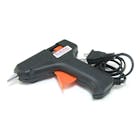
To make the body first I cut the box (rolling box). Then I cut some round pieces of card board to place the motor on each side (see picture 2 & 3). Then use sufficient amount of hot glue to secure everything in place. Also cut a place to add batteries and electronics inside. After that install the wheels. Now, you see the wheel just barely touches the ground so add some hot glue to make the wheel larger, looks kind of wheels ice trucks use (see last two pictures). Then paint it as you want, it's your robot baby ;). I used powder spray coat.
Step 4: The Circuit and Electronics
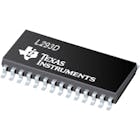
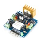
I have made it using L293d motor driver as it is too tiny and was suitable for small robots. But for your convenience I made the same circuit with L298n motor driver module (It's easier to use). Then I soldered everything on a vero board (look at pics).
find the images of circuits below.
Step 5: Uploading the Code & Download App
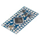
|| Now Arduino pro mini is cheapest that's why It doesn't come with usb programming option. You can upload code using a usb to TTL module but I like another way. You can use your arduino Uno to upload code to your arduino pro mini.
Steps:
Remove the Atmega IC
Uno 5v -- pro mini vcc
TX -- tx
RX -- rx
reset -- rst
<_e_1jU4><_e_1jU4>Download the code from https://github.com/ashraf-minhaj/LulaBot
or find the code below.
<_e_1jU4>Then Download the app from here.
Step 6: Final Step
Now open the app and then it'll ask to on bluetooth hit ok. Before you can connect ot HC05 you need to pair to that bluletooth module first. Open your bluetooth settings and then click pair (password is already given there).
I used 2 3.7v lithium batteries to make a 7.4v battery. You may use 7 to 9 v batteries.
Now have fun and please pray and subscribe if you have liked the robot.
Thanks a lot for reading.

 |
|

The LulaBot!
Step 1: Parts You'll Need
1. 3.3k and 2.2k resistor
<_e_1jU4><_e_1jU4>Note: The HC05 will survive 5v butit's 3.3v logic voltage devicethat's why I used 3.3k and 2.2k resistors to step down the voltage from 5v to almost 3.3v. Better save to than be sorry right?<_e_1jU4>for body I used a Badminton shuttle box
Step 2: Principle
This robot is wireless controlled. So the android app sends some characters and arduino reads them via the HC05 bluetooth module using Serial communication. Say I sent 'f' then coded the robot if it reads 'f' execute the forward statements. If no command do nothing means stop the robot.
Step 3: Make the Body
Don't know why I couldn't upload pictures to this site. Please watch the video to get to know I I made the body.
To make the body first I cut the box (rolling box). Then I cut some round pieces of card board to place the motor on each side (see picture 2 & 3). Then use sufficient amount of hot glue to secure everything in place. Also cut a place to add batteries and electronics inside. After that install the wheels. Now, you see the wheel just barely touches the ground so add some hot glue to make the wheel larger, looks kind of wheels ice trucks use (see last two pictures). Then paint it as you want, it's your robot baby ;). I used powder spray coat.
Step 4: The Circuit and Electronics
I have made it using L293d motor driver as it is too tiny and was suitable for small robots. But for your convenience I made the same circuit with L298n motor driver module (It's easier to use). Then I soldered everything on a vero board (look at pics).
find the images of circuits below.
Step 5: Uploading the Code & Download App
|| Now Arduino pro mini is cheapest that's why It doesn't come with usb programming option. You can upload code using a usb to TTL module but I like another way. You can use your arduino Uno to upload code to your arduino pro mini.
Steps:
Remove the Atmega IC
Uno 5v -- pro mini vcc
TX -- tx
RX -- rx
reset -- rst
<_e_1jU4><_e_1jU4>Download the code from https://github.com/ashraf-minhaj/LulaBot
or find the code below.
<_e_1jU4>Then Download the app from here.
Step 6: Final Step
Now open the app and then it'll ask to on bluetooth hit ok. Before you can connect ot HC05 you need to pair to that bluletooth module first. Open your bluetooth settings and then click pair (password is already given there).
I used 2 3.7v lithium batteries to make a 7.4v battery. You may use 7 to 9 v batteries.
Now have fun and please pray and subscribe if you have liked the robot.
Thanks a lot for reading.

