Magic Morse on Arduino
DESCRIPTION
Magic Morse Overview
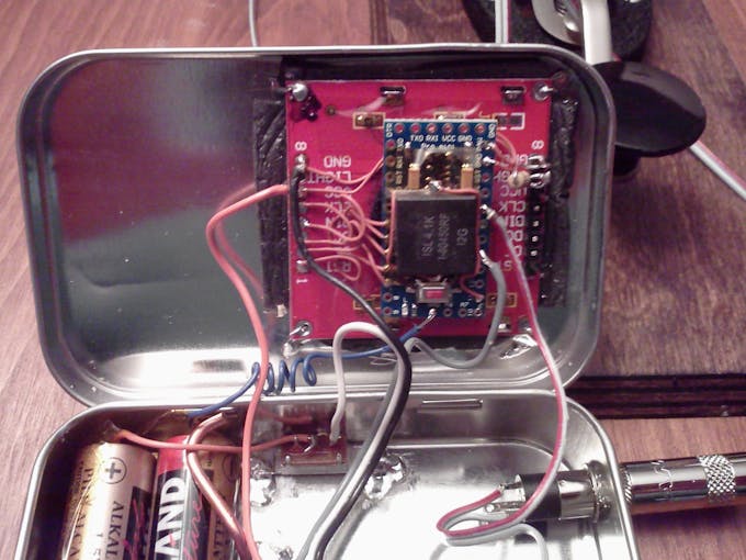
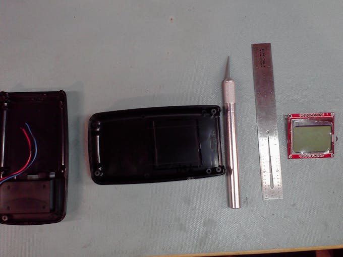
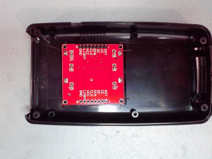
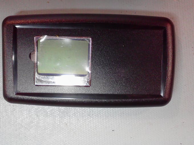
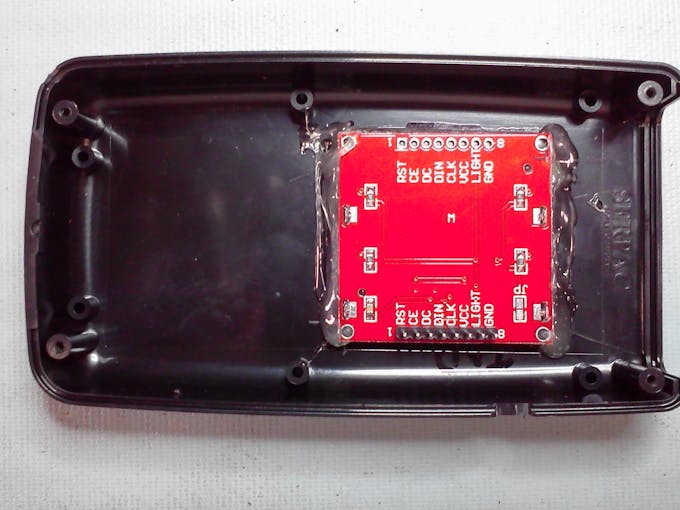
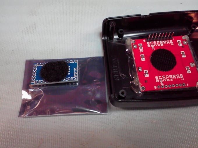
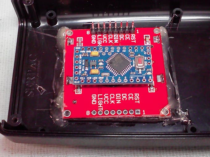
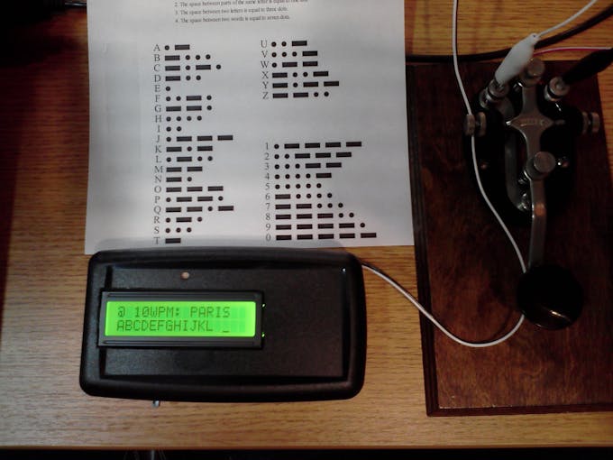
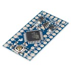
Magic Morse is a mathematical algorithm which I wrote a few years back to make it easy to implement both send and receive of Morse Code signals. Originally it was implemented in PIC but it has been fully rewritten and updated to work as a training program on the Arduino platform. It will run on Uno, Nano, Pro Micro, or your own homebrew board-duino. While I am showcasing the Nokia 5110 inexpensive black-n-white display, I will also post the code for those inexpensive 2x16 LCD parallel displays that are so common.
Essentially, the Magic Morse algorithm assigns a weight to dits and dahs as the stream is received. When a word space or longer is encountered, the algorithm instantly has a calculated pointer into an array stored in eeprom and the decoded character is returned. Magic Morse is a copyrighted algorithm but the Arduino code is Open Source and it is hoped you have lots of fun with this implementation.
The algorithm will generate a number between 1 and 255 for every Morse Code combination decoded. For every DAH identified in the stream, a binary weight is applied based upon the position of the DAH... that is, first, second, third, fourth, or fifth element. DITs are not weighted but are counted with DAHs to achieve a total element count of DITs + DAHs in the character. The DAH-weights are bits 3-7 in a calculated index and the elements number make up bits 0-2.
Examples:
E = "DIT" Therefore, there are no DAHs and only one element. The pointer is %00000001 Index = 1
F = "DIT DIT DAH DIT" and the DAH is in the third position (bit 5 set) Pointer = %00100100 Index = 36
Readers wishing to learn more about the algorithm implementation can refer to:
http://www.picaxeforum.co.uk/entry.php?30-Notes-behind-Magic-Morse
Source Code - Both Versions
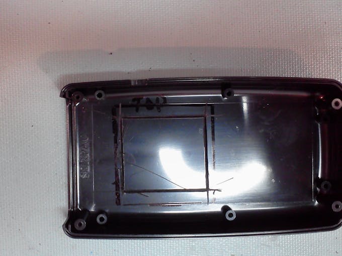
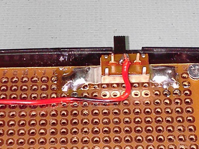
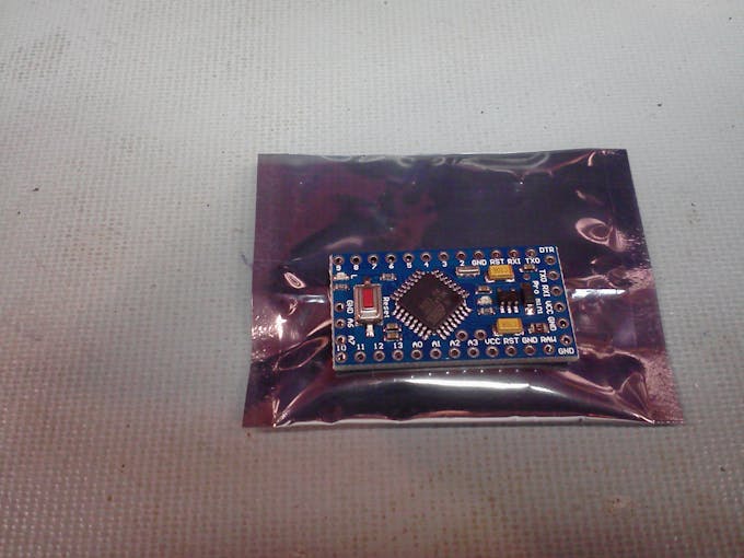
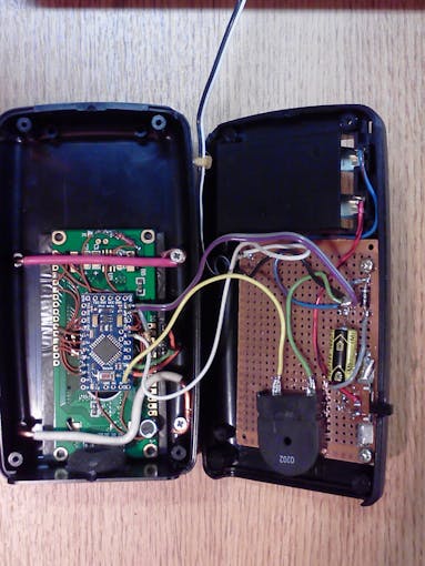
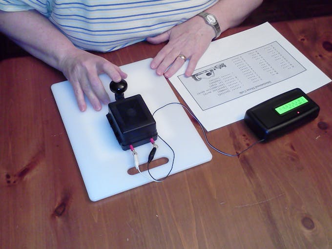
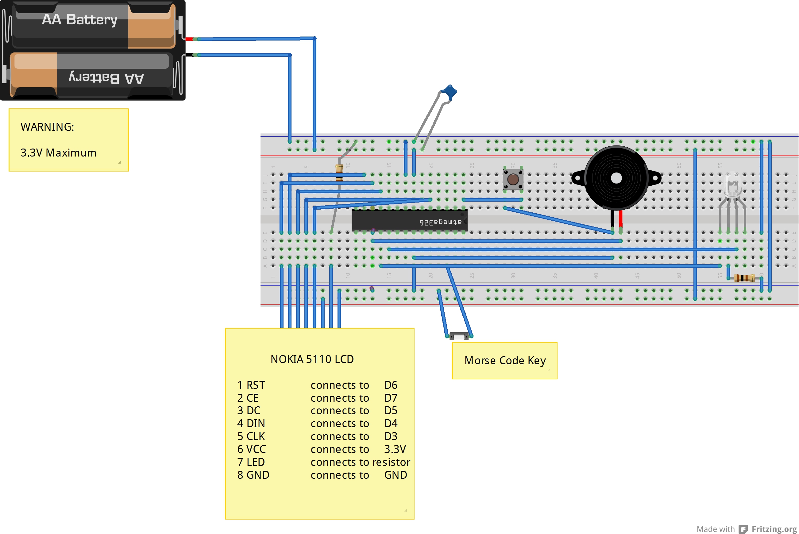
Building a Magic Morse Trainer
Notes and Credits: Advanced Project - connection info
Fritzing documents for 3.3V Nokia/Arduino (drafts)
Magic Morse Overview
Magic Morse is a mathematical algorithm which I wrote a few years back to make it easy to implement both send and receive of Morse Code signals. Originally it was implemented in PIC but it has been fully rewritten and updated to work as a training program on the Arduino platform. It will run on Uno, Nano, Pro Micro, or your own homebrew board-duino. While I am showcasing the Nokia 5110 inexpensive black-n-white display, I will also post the code for those inexpensive 2x16 LCD parallel displays that are so common.
Essentially, the Magic Morse algorithm assigns a weight to dits and dahs as the stream is received. When a word space or longer is encountered, the algorithm instantly has a calculated pointer into an array stored in eeprom and the decoded character is returned. Magic Morse is a copyrighted algorithm but the Arduino code is Open Source and it is hoped you have lots of fun with this implementation.
The algorithm will generate a number between 1 and 255 for every Morse Code combination decoded. For every DAH identified in the stream, a binary weight is applied based upon the position of the DAH... that is, first, second, third, fourth, or fifth element. DITs are not weighted but are counted with DAHs to achieve a total element count of DITs + DAHs in the character. The DAH-weights are bits 3-7 in a calculated index and the elements number make up bits 0-2.
Examples:
E = "DIT" Therefore, there are no DAHs and only one element. The pointer is %00000001 Index = 1
F = "DIT DIT DAH DIT" and the DAH is in the third position (bit 5 set) Pointer = %00100100 Index = 36
Readers wishing to learn more about the algorithm implementation can refer to:
http://www.picaxeforum.co.uk/entry.php?30-Notes-behind-Magic-Morse
Source Code - Both Versions
Building a Magic Morse Trainer