Mini Laser Engraver on 28BYJ-48 Motors © MIT
DESCRIPTION
From my previous ARDUINO projects I got a lot of hardware that laid in the basis of this toy. It has helped me to familiarize with the fundamentals of g-code, various free software and its settings.
The toy is shown in Fig. 1.
MechanicsAs the title says, the toy incorporates two unipolar steppers 28byj-48 (Fig. 2).
Four 125mm pieces of 8mm precise shaft were used as well as four linear bearings LM8UU. All this stuff is joined with cable ties (Fig. 3).
Since steppers are very slow, a belt drive was the best choice (Fig. 4).
There are no tensioners in the design so the proper operation is provided with accurate adjustment of the belt’s length. Ends of the belt are bonded with super glue. As an opposite pulley two ball bearings (inner diameter 4mm, outer diameter 13mm, width 5mm) are used (Fig. 5).
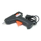
A 3.5’’ floppy disk serves as a table. The approximate size of working area is 80x80mm. The table is mounted onto small pinewood pieces with hot glue (Fig. 6).
As you might have noticed, the frame is made of metal constructor (Fig. 7). It is important not to breathe near the toy, then everything will be going well)
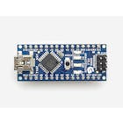
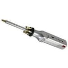
ElectronicsA list of electronic components (Fig. 8):
And a laser module of course (Fig. 9)! I used violet(405nm) laser module of 1W power declared. Do not forget following all safety precautions when working with it!
The circuit diagram is show in Fig. 10.
Firmware for ARDUINO boardWhile I’m writing this, the toy operates on GRBL 0.9jservo – a fork of standard GRBL for support of servomotor and two 28byj-48steppers (link: https://github.com/ruizivo/GRBL-28byj-48-Servo).
This modification is intended for 2D-plotters where the servo controls a pen moving it up and down. The servo itself is controlled with PWM on D11, but we can replace a pen with a laser.
There is also another fork, based on far newer GRBL 1.1f (with optimized Laser mode implemented ), for three 28byj-48 steppers (link: https://github.com/TGit-Tech/GRBL-28byj-48). But I found that PWM does not work here. I think this is due to hack for the third axis support. That is why I had to stay on GRBL 0.9j.
To work with the laser I changed some settings in GRBL source files:
- «spindle_control.c»: unlike the servo we need allPWM range (Fig. 11). In addition I increased PWM frequency up to 980Hz (Fig. 12);
- «config.h»: check if VARIABLE_SPINDLE parameter is defined (responsible for PWM), and set the maximum spindle RPM as 255 (Fig. 13);
The firmware is added in ARDUINO IDE trough «Sketch»> «Include libary» > «Add ZIP library», then select «grbl» folder from the archive.
Software for PCGRBL receives commands from a computer through USB connection. That is why we have to use a special software such as:
- Universal G-code Sender, UGS (http://winder.github.io/ugs_website/download/) – works with g-code files;
- LaserGRBL (http://lasergrbl.com/download/) – capable either to transform a raster image to CNC commands or to manage with g-code files directly.
Additionally I recommend:
- Inkscape (https://inkscape.org/) – vector graphics editor with g-code generation plugins available (though I could not made them working properly);
- DXF2GCODE (https://sourceforge.net/projects/dxf2gcode/) – converts dxf files to g-code. Many CAD programs support dxf files.
Before doing anything with our toy it is necessary to define an important parameter in GRBL: number of steps per millimeter along X and Y axes. Connect ARDUINO board through «Grbl» >«Connect», then select «Grbl» > «Grbl configuration» (Fig. 14).
As the initial value we can calculate:
n = N*R / (π*D),
where N = 64 – number of steps per 1 round for 28byj-48stepper;
R ≈ 64 – ratio for reducer of 28byj-48 stepper;
D – diameter of belt pulley, mm (12mm in my case).
After the first test burning the initial value was altered to 103, 476 step/mm.
After all changes has been made hit the «Write» button to download new data into microcontroller’s memory.
Final step: laser focusing. As it is stated in the official documentation (https://github.com/robottini/grbl-servo) PWM is set by the command M3 SXXX, where XXX – number from 0 to 255 (i.e. 0 – minimal and255 – maximal power).
To focus the laser we do not need the maximal power so just type, for example, M3 S10 in the special field in LaserGRBL (Fig. 15).
We get a weak but visible light spot which then can be adjusted to the minimal size using ring on the module.
Send M5 command when it is done. Now our toy is ready to burn.
Open raster image in LaserGRBL:«File» > «Open File» (Fig. 16). I used logo of Faculty of Rocket and Space Engineering(https://khai.edu/ua/education/fakultety-i-kafedry/fakultet-raketno-kosmichnoi-tehniki/) of National Aerospace University «Kharkiv Aviation Institute».
Process the image with filters available in LaserGRBL (Fig. 17). The description of all settings can be found at the official website of the program.
Click «Next» and define Engraving speed, Laser options, Offsets and Sizes of the image (Fig. 18).
After hitting «Create!» button we get visualization of laser trajectories. Since there are no end stops, before burn something, check twice the position of the laser module (its current position is marked as «plus»). To adjust the position a pad in the left bottom corner and «Set New Zero» button should be used (Fig. 19).
Select «File» > «Send To Machine» and enjoy the process. It may take hours depending on line density, image size. And do not forget about how slow our steppers are.
After several tests on plywood I thought it would be nice to have a logo on phone’s rear cover (Fig. 20).
The video of engraving process:
 |
| × | 1 | |||
| × | 2 | ||||
| × | 2 | ||||
| × | 1 | ||||
| × | 1 | ||||
| × | 4 | ||||
| × | 4 | ||||
| × | 1 | ||||
| × | 4 | ||||
| × | 4 | ||||
| × | 2 | ||||
| × | 2 | ||||
| × | 1 | ||||
| × | 1 |
From my previous ARDUINO projects I got a lot of hardware that laid in the basis of this toy. It has helped me to familiarize with the fundamentals of g-code, various free software and its settings.
The toy is shown in Fig. 1.
MechanicsAs the title says, the toy incorporates two unipolar steppers 28byj-48 (Fig. 2).
Four 125mm pieces of 8mm precise shaft were used as well as four linear bearings LM8UU. All this stuff is joined with cable ties (Fig. 3).
Since steppers are very slow, a belt drive was the best choice (Fig. 4).
There are no tensioners in the design so the proper operation is provided with accurate adjustment of the belt’s length. Ends of the belt are bonded with super glue. As an opposite pulley two ball bearings (inner diameter 4mm, outer diameter 13mm, width 5mm) are used (Fig. 5).
A 3.5’’ floppy disk serves as a table. The approximate size of working area is 80x80mm. The table is mounted onto small pinewood pieces with hot glue (Fig. 6).
As you might have noticed, the frame is made of metal constructor (Fig. 7). It is important not to breathe near the toy, then everything will be going well)
ElectronicsA list of electronic components (Fig. 8):
And a laser module of course (Fig. 9)! I used violet(405nm) laser module of 1W power declared. Do not forget following all safety precautions when working with it!
The circuit diagram is show in Fig. 10.
Firmware for ARDUINO boardWhile I’m writing this, the toy operates on GRBL 0.9jservo – a fork of standard GRBL for support of servomotor and two 28byj-48steppers (link: https://github.com/ruizivo/GRBL-28byj-48-Servo).
This modification is intended for 2D-plotters where the servo controls a pen moving it up and down. The servo itself is controlled with PWM on D11, but we can replace a pen with a laser.
There is also another fork, based on far newer GRBL 1.1f (with optimized Laser mode implemented ), for three 28byj-48 steppers (link: https://github.com/TGit-Tech/GRBL-28byj-48). But I found that PWM does not work here. I think this is due to hack for the third axis support. That is why I had to stay on GRBL 0.9j.
To work with the laser I changed some settings in GRBL source files:
- «spindle_control.c»: unlike the servo we need allPWM range (Fig. 11). In addition I increased PWM frequency up to 980Hz (Fig. 12);
- «config.h»: check if VARIABLE_SPINDLE parameter is defined (responsible for PWM), and set the maximum spindle RPM as 255 (Fig. 13);
The firmware is added in ARDUINO IDE trough «Sketch»> «Include libary» > «Add ZIP library», then select «grbl» folder from the archive.
Software for PCGRBL receives commands from a computer through USB connection. That is why we have to use a special software such as:
- Universal G-code Sender, UGS (http://winder.github.io/ugs_website/download/) – works with g-code files;
- LaserGRBL (http://lasergrbl.com/download/) – capable either to transform a raster image to CNC commands or to manage with g-code files directly.
Additionally I recommend:
- Inkscape (https://inkscape.org/) – vector graphics editor with g-code generation plugins available (though I could not made them working properly);
- DXF2GCODE (https://sourceforge.net/projects/dxf2gcode/) – converts dxf files to g-code. Many CAD programs support dxf files.
Before doing anything with our toy it is necessary to define an important parameter in GRBL: number of steps per millimeter along X and Y axes. Connect ARDUINO board through «Grbl» >«Connect», then select «Grbl» > «Grbl configuration» (Fig. 14).
As the initial value we can calculate:
n = N*R / (π*D),
where N = 64 – number of steps per 1 round for 28byj-48stepper;
R ≈ 64 – ratio for reducer of 28byj-48 stepper;
D – diameter of belt pulley, mm (12mm in my case).
After the first test burning the initial value was altered to 103, 476 step/mm.
After all changes has been made hit the «Write» button to download new data into microcontroller’s memory.
Final step: laser focusing. As it is stated in the official documentation (https://github.com/robottini/grbl-servo) PWM is set by the command M3 SXXX, where XXX – number from 0 to 255 (i.e. 0 – minimal and255 – maximal power).
To focus the laser we do not need the maximal power so just type, for example, M3 S10 in the special field in LaserGRBL (Fig. 15).
We get a weak but visible light spot which then can be adjusted to the minimal size using ring on the module.
Send M5 command when it is done. Now our toy is ready to burn.
Open raster image in LaserGRBL:«File» > «Open File» (Fig. 16). I used logo of Faculty of Rocket and Space Engineering(https://khai.edu/ua/education/fakultety-i-kafedry/fakultet-raketno-kosmichnoi-tehniki/) of National Aerospace University «Kharkiv Aviation Institute».
Process the image with filters available in LaserGRBL (Fig. 17). The description of all settings can be found at the official website of the program.
Click «Next» and define Engraving speed, Laser options, Offsets and Sizes of the image (Fig. 18).
After hitting «Create!» button we get visualization of laser trajectories. Since there are no end stops, before burn something, check twice the position of the laser module (its current position is marked as «plus»). To adjust the position a pad in the left bottom corner and «Set New Zero» button should be used (Fig. 19).
Select «File» > «Send To Machine» and enjoy the process. It may take hours depending on line density, image size. And do not forget about how slow our steppers are.
After several tests on plywood I thought it would be nice to have a logo on phone’s rear cover (Fig. 20).
The video of engraving process:


