Minimal MIDI Drum Kit with 3D Printer © GPL3+
DESCRIPTION
Hi.
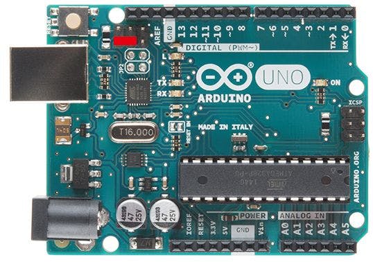
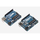
This is minimal drum kit using arduino UNO.
First of all, please check this instructables page.
https://blog.arduino.cc/2017/01/19/a-3d-printed-e-drum-pad/
Since I started making this, I was captivated by piezo and electronic drums.
I was fascinated by a very simple mechanism of electronic drums and the great invention called MIDI.
In other words, I could not be satisfied just by making pads.
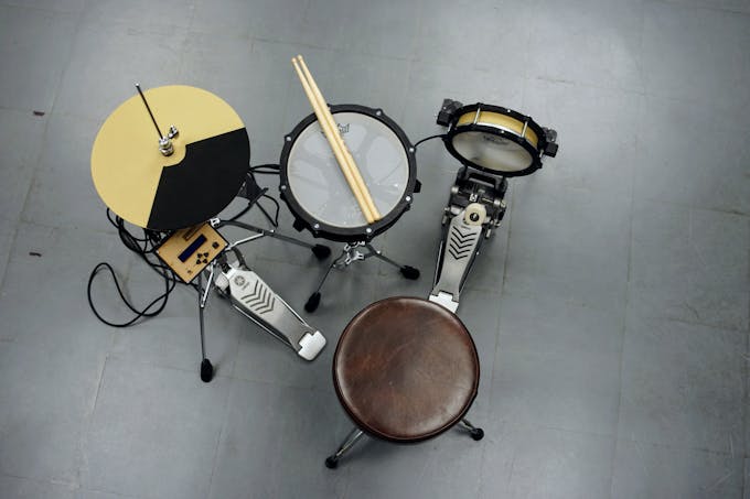
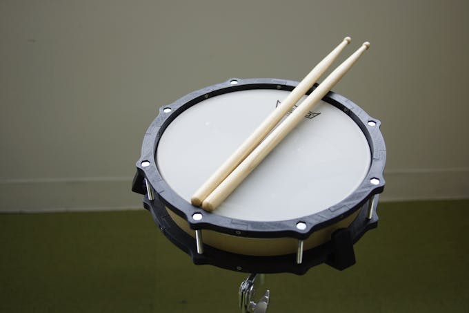
This drum kit is roughly divided into two productions.
1.Pad made with a 3d printer and thick paper.
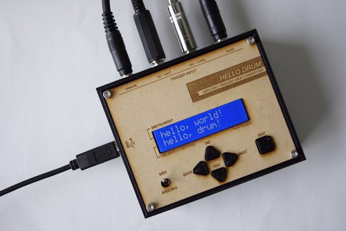
2.Trigger midi converter with arduino UNO .
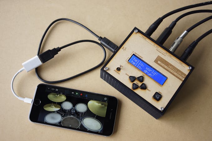
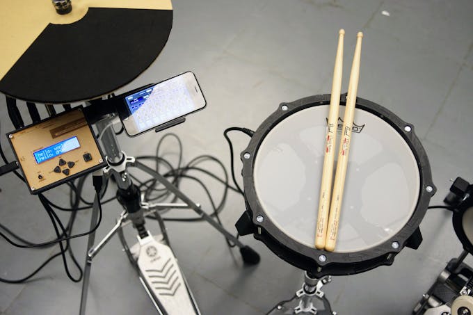
The signal sent from the pad of " 1 " is processed by arduino of " 2 " and converted into MIDI signal. And the MIDI signal is transmitted from arduino to iPhone, laptop, etc, and sound comes out.
You do not need to prepare a power supply other than a smartphone or PC.
What You'll Need
Tools
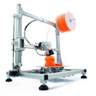
・3D Printer
・Laser Cutter (Extra)
・hex wrench
・cutter knife
・circle cutter
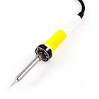
・Soldering Iron
・Pipe Cutter
・driver drill
・drill bit 9mm / 10mm
Material
・1mm thick paper
・PLA filament
・Sponge Foam Sheets 5mm / 10mm
・MDF 2.5mm / 5.5mm (Extra)
・M6 - 70mm bolt and nuts
・M6 - 50mm bolt and nuts
・M3 - 10mm bolt and nuts
・M3 - 15mm bolt and nuts
・M3 - 25mm bolt and nuts
・M2 screw
・13 mm diameter Stainless steel pipe
Drum Hardware
・Mesh head 10 inch / 8 inch
・Snare stand (Anything is OK. I am using YAMAHA SS662.)
・Hi-hat stand (Anything is OK. I am using YAMAHA HS650A)
・Kick pedal (Anything is OK. I am using YAMAHA FP7210A)
・Drum stick
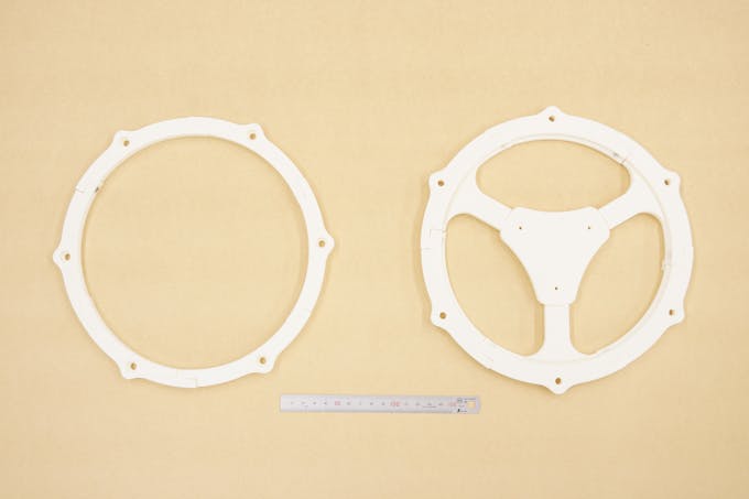
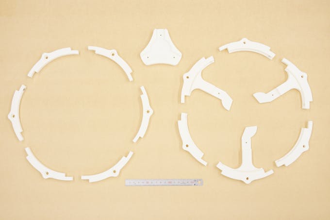
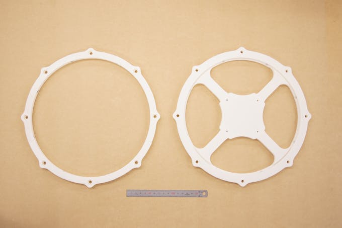
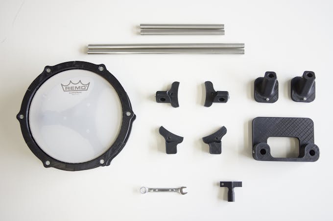
Step 1 : 3D PrintingAll data is on Thingiverse and GitHub.
Please use Ver.2 for the rim.
I printed parts with infill at 20%. The thickness of the layer is 0.3 mm.
Also, you can use laser cutter for making pad.
https://github.com/RyoKosaka/drums/tree/master/vector
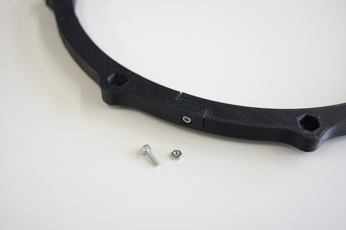
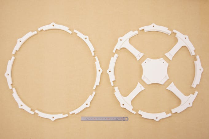
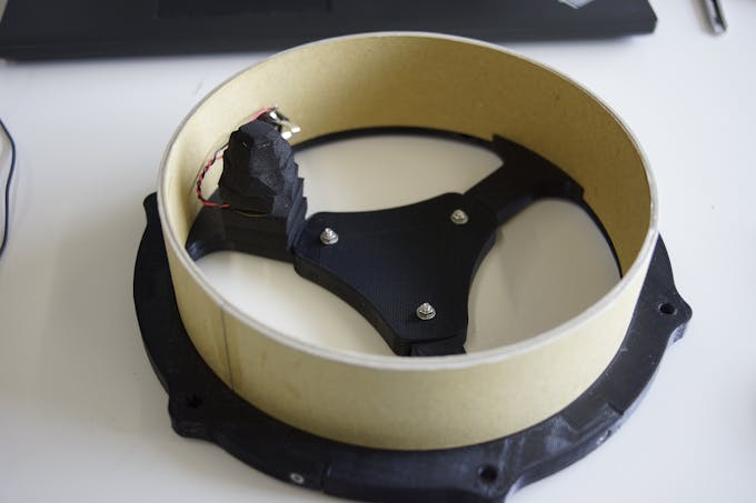
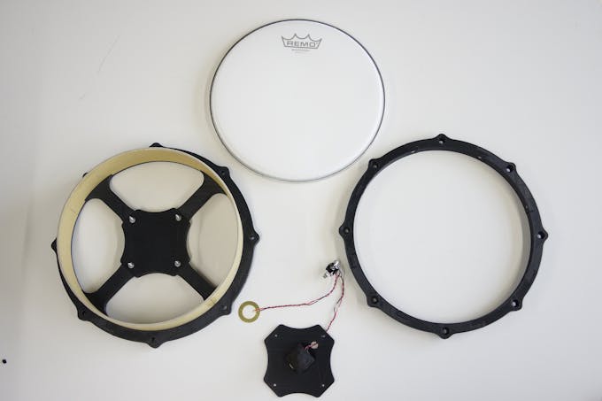
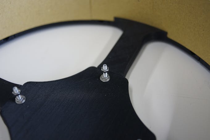
Step 2 : AssemblingUse M3-10mm bolts and nuts to connect the parts together.
Use the M3-15 mm or M3-25 mm bolts for the center part to fix the bottom part to each other.
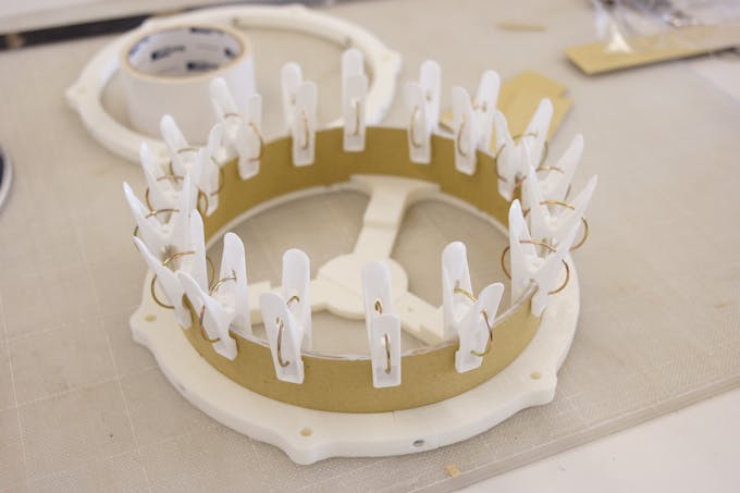
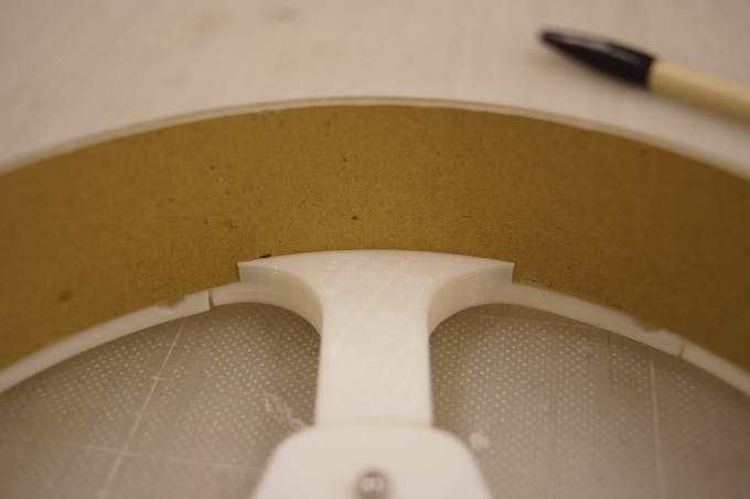
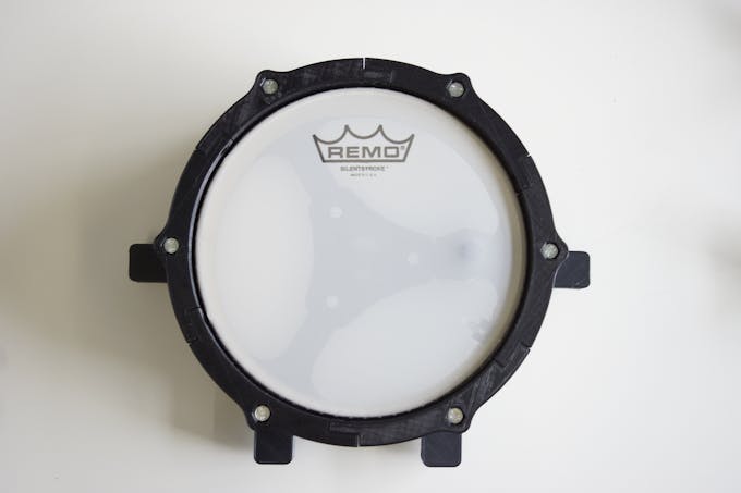
First, the height of the shell is 55 mm.
Please make three bands with a width of 55 mm.
The length is slightly longer than the length covering the pad.
Since there is a gap at the bottom, try inserting one band into that gap.
Cut the band so that it will be perfect circle length.
Repeat this 3 times and overlay using adhesive.
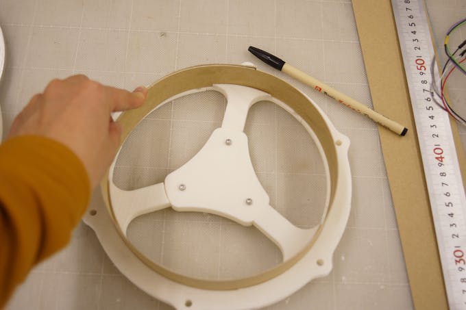
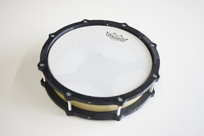
When the shell dries, with the mesh head fixed, make a hole of 9 mm in diameter for the socket.
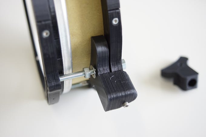
You can use butterfly nuts, but I also made tuning keys that can be tightened even with ordinary nuts, so please use it by all means.
For fixing the mesh head, use M6-70 mm bolts.
Once you've made a hole, remove the mesh head again to put a piezo
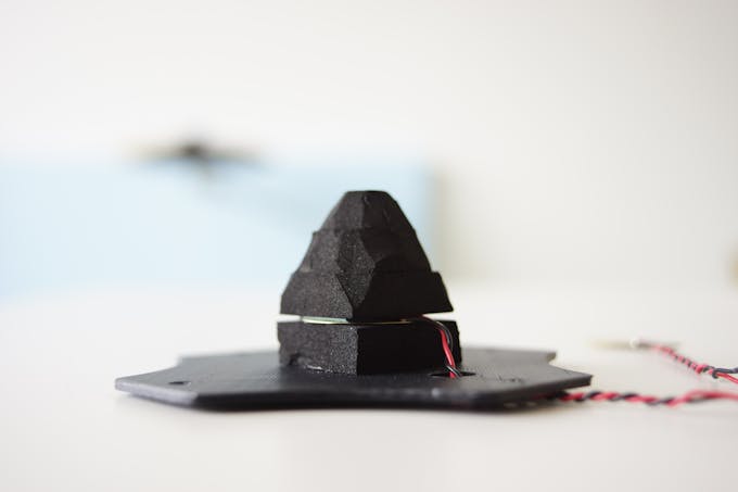
SNARE
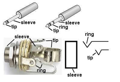
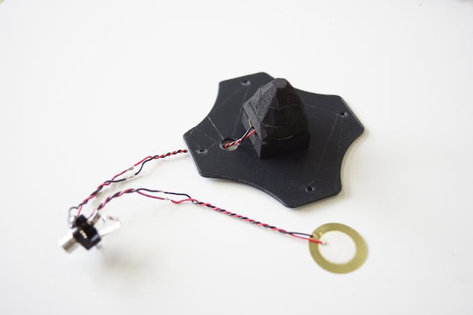
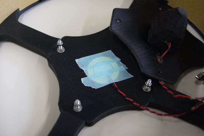
In the case of a snare, use two piezo as shown in the picture.
Connect piezo's red cable to each of tip and ring.
Both black cables connect to sleeve.
Do not forget to thread the cables through the holes in the sensor plate when soldering.
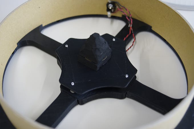
Piezo for the head (piezo connected to tip) needs to be sandwiched with 10 mm thick sponge foam as shown in the picture.
One below, three on the top. And make the top 3 cones like the picture.
Then put it on the sensor plate.
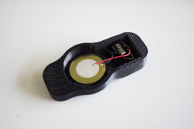
KICK
Since the kick pad uses only one piezo, only tip can be used.
No sensor plate is required.Two sponge foams under the piezo
Place the sensor offset from the center.
It is because arduino can not judge the strength of hit if beater hits sensor directly.
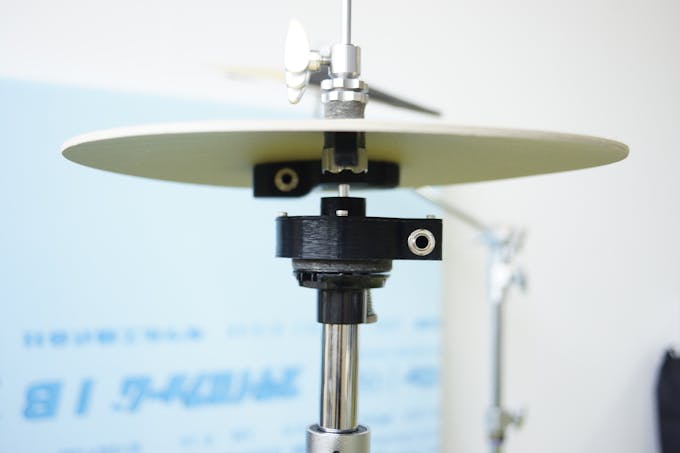
HI-HAT
The circuit is the same as the kick pad.
Put a piece of 10 mm thick sponge foam under the piezo.
Piezo is delicate. Be careful not to bend or hurt.
First attach the sensor for the rim.
Fix the sensor plate. Firmly fix it. Make the end of the cone visible 2-3 mm when viewed from the side.
Of course, the same procedure is also used when using an 8-inch pad as a snare.
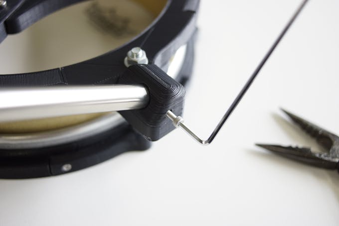
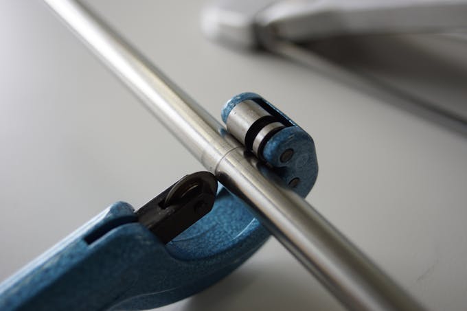
First, cut a 13 mm diameter stainless steel pipe.
Make two 200 mm and two 365 mm.
Since the length can be adjusted, even if there is some error in the length, it is OK.
Assemble them with reference to pictures.
In order to fix the pipe, it is designed so that the M3 nut can be loaded inside the part.
Fix the pipe securely. Use M3-15 mm bolts and nuts.
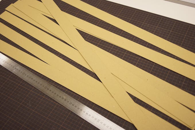
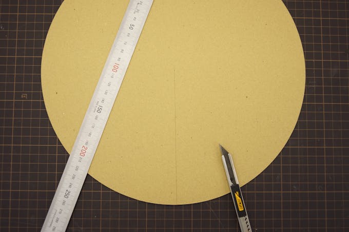
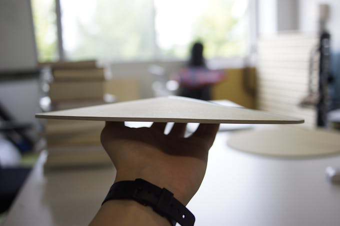
After producing the shell with thick paper, I thought that if you use thick paper I can make cymbals.
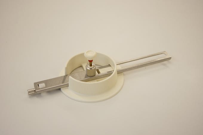
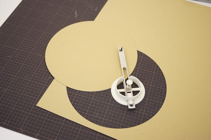
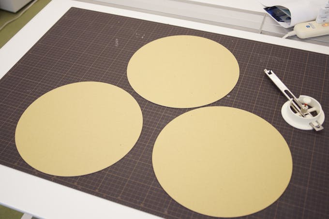
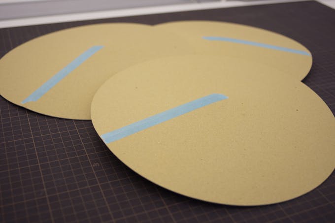
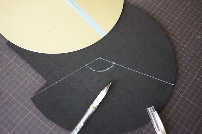
First. Cut thick paper into a circle with a diameter of 300 mm. Make three of this.
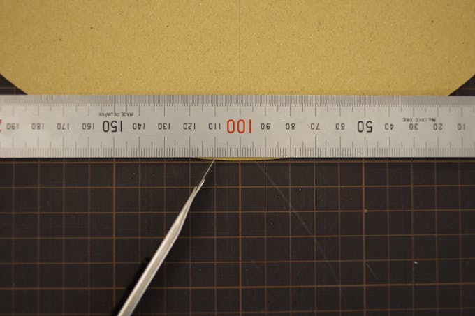
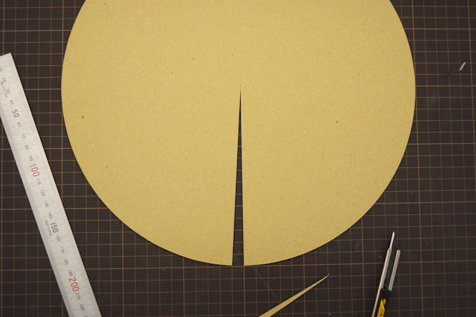
Next, make a notch from the center.
Finally, a second notch is made from the point 10 mm apart parallel from the first notch.
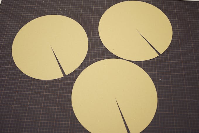
In this way, three pac-mans with a small mouth opened are made.
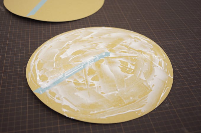
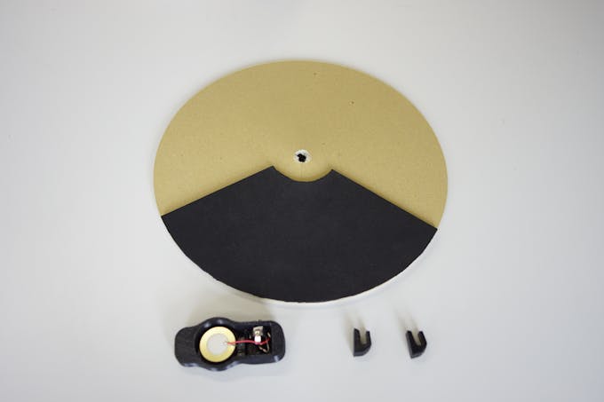
Then close the Pac Man's mouth carefully with tape to make it into a cymbal shape.
Apply adhesive and overlay these.Do not forget to extend the adhesive cleanly and thinly
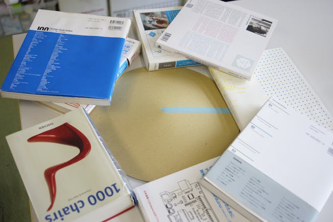
Hold firmly with your hands, then place the weight around and dry.
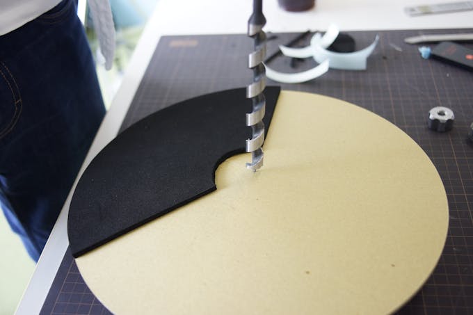
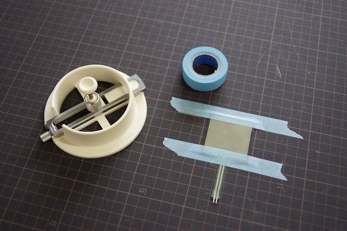
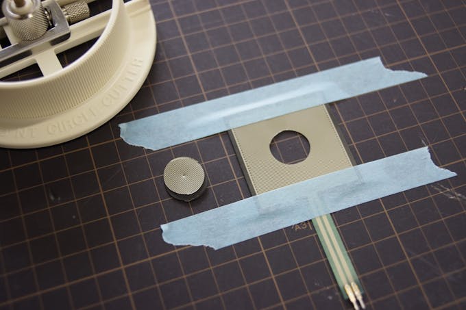
For silencing, put a 5 mm thick sponge and drill a hole. You can not open the hole neatly, but you can hide the hole so it's okay.
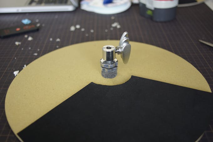
Complete by attaching sensor mount and cable guide with double-sided tape. It might be easier if you use glue gun.
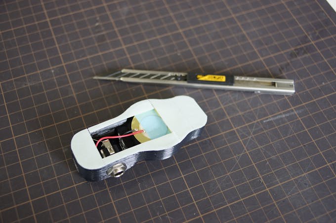
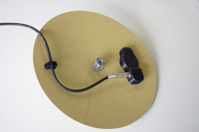
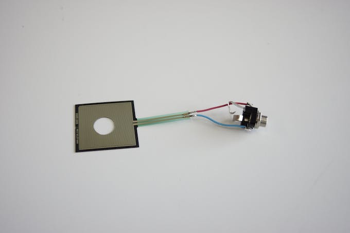
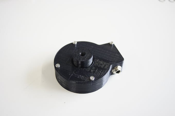
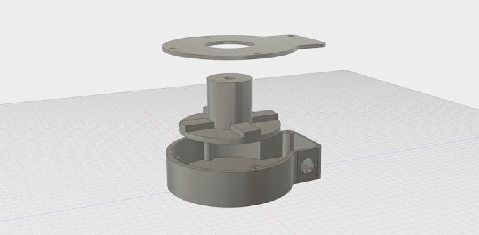
Hi-Hat Controller sends the opening and closing of the hi-hat to arduino.
The circuit is very simple.
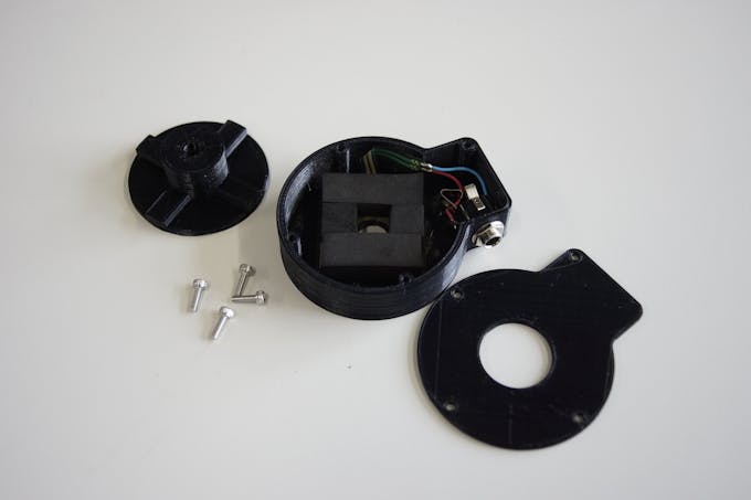
It is made by combining three parts.
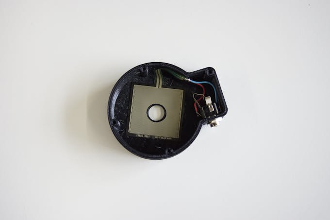
Attach the FSR to the bottom part and fix the socket. FSR can be used even if a hole is opened.
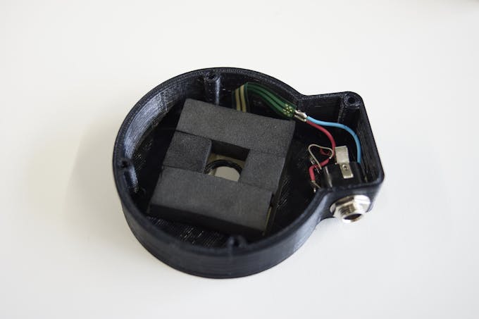
Attach a 10 mm sponge to the FSR like a photo.
Fix the cover with M3 - 10 mm bolts.
Even though it's only HIGH and LOW, you may wonder why I used FSR.
I use FSR to correspond to sound modules such as Roland and Yamaha.
And in the sound source exclusive for drums such as EZ DRUMMER 2, there are several stages in the degree of opening of the hi-hat.
If it is FSR, it may be possible to respond by just modifying the code. However, I have not tried it.
What can we do in this step?
With usb cable alone, you can send midi signal from arduino.
In other words, make arduino be recognized by iPhone etc. as a midi device without any additional hardware.
First of all, check this page.
http://morecatlab.akiba.coocan.jp/lab/index.php/aruino/midi-firmware-for-arduino-uno-moco/
https://github.com/kuwatay/mocolufa
If you connect normal arduino UNO directly to iPhone, you will get an error message like "Arduino UNO is not compatible".
So, you have to rewrite the USB chip (ATmega16U2) used in arduino UNO.
https://www.arduino.cc/en/Hacking/DFUProgramming8U2
This instruction is how to rewrite the hex file.
Please proceed according to this site until the description below.
sudo dfu-programmer atmega16u2 flash Arduino-usbserial-uno.hex
Just replace "Arduino-usbserial-uno.hex" with "dualMoco.hex".
Therefore,
sudo dfu-programmer atmega16u2 flash dualMoco.hex
After rewriting, your Arduino will be recognized as a MIDI device.
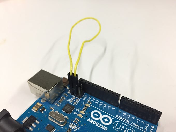
If you short-circuit the pin as shown in the picture, it will be recognized as normal Arduino.
If not (when not short-circuited), arduino UNO will be recognized as a MIDI device.
In other words, when writing code using the arduino IDE, you have to short-circuit the pins as shown in the picture.
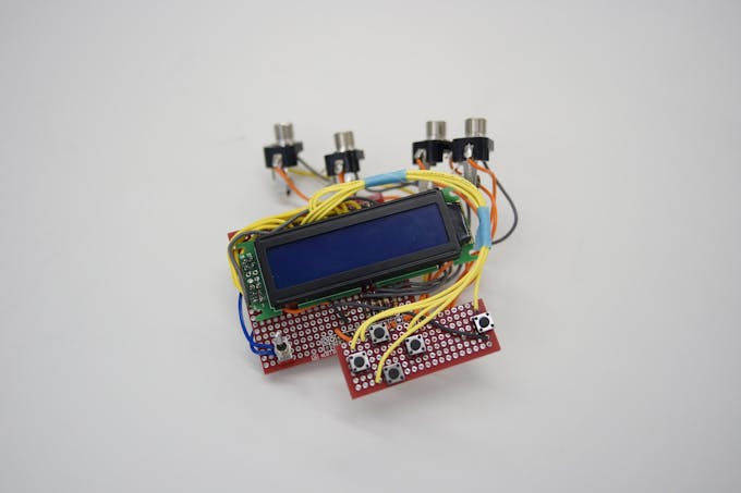
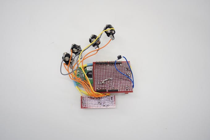
There is arduino UNO and shield in the box.
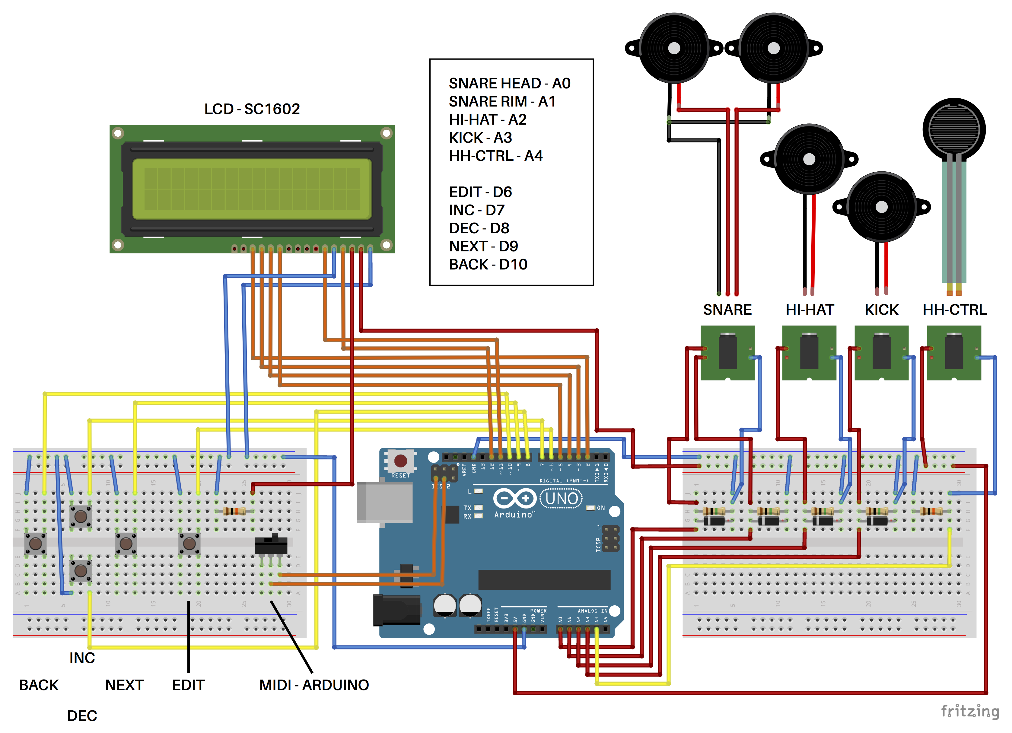
Refer to the image of fritzing for the circuit of the shield.
Diodes are for protection but I saw the information that arduino UNO has protection circuit, diodes may not be necessary. Does anyone know about this?
After printing the model of the case and the cover first, it is good to make the shield according to it.
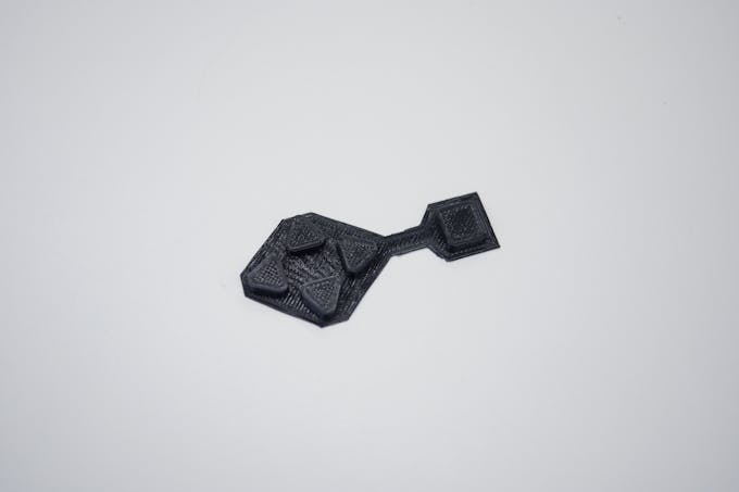
There is also a 3D model of the cover, but I made a cover with a laser cutter. Please choose whichever you like.
Just start garageband and connect. There is no particularly difficult setting.
There are a number of DAWs for PCs that can be used on this drum set, including GarageBand.
Among them, Hydrogen is free and you can add sound.
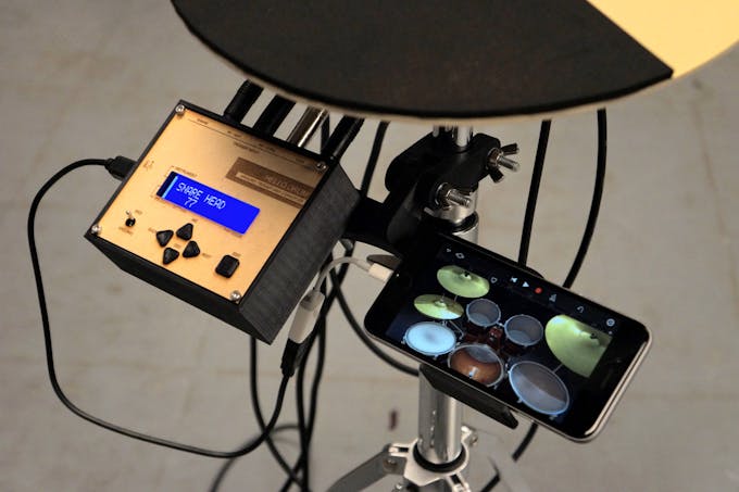
Step 12 : SettingIn making the code, it was troublesome to rewrite the code each time the value changed, so I wanted to be able to change the value with arduino alone.
In other words, this is made for debugging code, so there are items that do not need to be changed.
Nevertheless, setting is necessary depending on the size of the piezo, the size of the pad, the hardness of the sponge foam.
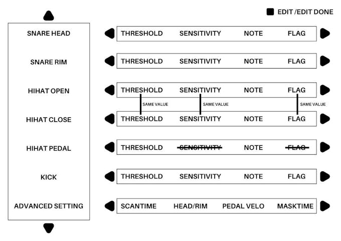
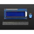
Select an instrument with the INC / DEC button and select the setting item with the NEXT / BACK button. When the EDIT button is pressed while the instruments and items you want to set are displayed, you can change the value with the INC / DEC button. Then, pressing the EDIT button again confirms the change.
If you watch at the latter part of the video you will understand how to operate.
THRESHOLD
The lowest value at which sound comes out
SENSITIVITY
Sensor sensitivity. If you lower it, you will gain high velocity even if you hit softly.
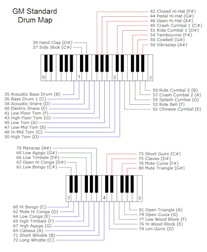
Number of the note. By changing, you can change instruments. Please refer to the image.
FLAG
A value for judging that the beating is over. You do not have to change it too much. It would be nice to set the value from 1 to 10. If you raise the value too much, you will get a sound twice with a single hit. If you lower it too much, you may get out of sound when you hit repeatedly.
SCAN TIME
In searching for peaks, values are taken consecutively for several milliseconds after exceeding the threshold. The highest value among them will peak. This several milliseconds is SCANTIME. There is no need to change it.
HEAD / RIM
Set the ease of the rim. Raising it makes it difficult to sound. If you lower it too hard the rim will sound when you hit the head. Regarding the judgment of the head and the rim, it may be necessary to improve the code
PEDAL VELO
Unlike other pads, the velocity of the pedal is constant. The initial value is 100. Please change to your favorite value.
MASK TIME
This is a value related to FLAG. There is no need to change it. If you raise it, you may not hear a sound when you hit continuously.
Some parts may not be usable unless their dimensions are changed. It is difficult to edit STL data. So I uploaded fusion 360 data. However, since I am editing data while trial and error, it is better not to depend too much on the history function.
https://github.com/RyoKosaka/drums/tree/master/Fusion360
EXTRAExtra steps are on instructables.
https://www.instructables.com/id/Arduino-Minimal-Drum-Kit/
And, detailed production process is published on this blog.
Check it if you are interested.
Please feel free to ask anything.
Have fun!
 |
| |||
 |
| |||
 |
| |||
|

Hi.
This is minimal drum kit using arduino UNO.
First of all, please check this instructables page.
https://blog.arduino.cc/2017/01/19/a-3d-printed-e-drum-pad/
Since I started making this, I was captivated by piezo and electronic drums.
I was fascinated by a very simple mechanism of electronic drums and the great invention called MIDI.
In other words, I could not be satisfied just by making pads.
This drum kit is roughly divided into two productions.
1.Pad made with a 3d printer and thick paper.
2.Trigger midi converter with arduino UNO .
The signal sent from the pad of " 1 " is processed by arduino of " 2 " and converted into MIDI signal. And the MIDI signal is transmitted from arduino to iPhone, laptop, etc, and sound comes out.
You do not need to prepare a power supply other than a smartphone or PC.
What You'll Need
Tools
・3D Printer
・Laser Cutter (Extra)
・hex wrench
・cutter knife
・circle cutter
・Soldering Iron
・Pipe Cutter
・driver drill
・drill bit 9mm / 10mm
Material
・1mm thick paper
・PLA filament
・Sponge Foam Sheets 5mm / 10mm
・MDF 2.5mm / 5.5mm (Extra)
・M6 - 70mm bolt and nuts
・M6 - 50mm bolt and nuts
・M3 - 10mm bolt and nuts
・M3 - 15mm bolt and nuts
・M3 - 25mm bolt and nuts
・M2 screw
・13 mm diameter Stainless steel pipe
Drum Hardware
・Mesh head 10 inch / 8 inch
・Snare stand (Anything is OK. I am using YAMAHA SS662.)
・Hi-hat stand (Anything is OK. I am using YAMAHA HS650A)
・Kick pedal (Anything is OK. I am using YAMAHA FP7210A)
・Drum stick
Step 1 : 3D PrintingAll data is on Thingiverse and GitHub.
Please use Ver.2 for the rim.
I printed parts with infill at 20%. The thickness of the layer is 0.3 mm.
Also, you can use laser cutter for making pad.
https://github.com/RyoKosaka/drums/tree/master/vector
Step 2 : AssemblingUse M3-10mm bolts and nuts to connect the parts together.
Use the M3-15 mm or M3-25 mm bolts for the center part to fix the bottom part to each other.
First, the height of the shell is 55 mm.
Please make three bands with a width of 55 mm.
The length is slightly longer than the length covering the pad.
Since there is a gap at the bottom, try inserting one band into that gap.
Cut the band so that it will be perfect circle length.
Repeat this 3 times and overlay using adhesive.
When the shell dries, with the mesh head fixed, make a hole of 9 mm in diameter for the socket.
You can use butterfly nuts, but I also made tuning keys that can be tightened even with ordinary nuts, so please use it by all means.
For fixing the mesh head, use M6-70 mm bolts.
Once you've made a hole, remove the mesh head again to put a piezo
SNARE
In the case of a snare, use two piezo as shown in the picture.
Connect piezo's red cable to each of tip and ring.
Both black cables connect to sleeve.
Do not forget to thread the cables through the holes in the sensor plate when soldering.
Piezo for the head (piezo connected to tip) needs to be sandwiched with 10 mm thick sponge foam as shown in the picture.
One below, three on the top. And make the top 3 cones like the picture.
Then put it on the sensor plate.
KICK
Since the kick pad uses only one piezo, only tip can be used.
No sensor plate is required.Two sponge foams under the piezo
Place the sensor offset from the center.
It is because arduino can not judge the strength of hit if beater hits sensor directly.
HI-HAT
The circuit is the same as the kick pad.
Put a piece of 10 mm thick sponge foam under the piezo.
Piezo is delicate. Be careful not to bend or hurt.
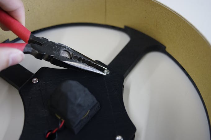
First attach the sensor for the rim.
Fix the sensor plate. Firmly fix it. Make the end of the cone visible 2-3 mm when viewed from the side.
Of course, the same procedure is also used when using an 8-inch pad as a snare.
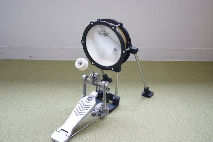
First, cut a 13 mm diameter stainless steel pipe.
Make two 200 mm and two 365 mm.
Since the length can be adjusted, even if there is some error in the length, it is OK.
Assemble them with reference to pictures.
In order to fix the pipe, it is designed so that the M3 nut can be loaded inside the part.
Fix the pipe securely. Use M3-15 mm bolts and nuts.
After producing the shell with thick paper, I thought that if you use thick paper I can make cymbals.
First. Cut thick paper into a circle with a diameter of 300 mm. Make three of this.
Next, make a notch from the center.
Finally, a second notch is made from the point 10 mm apart parallel from the first notch.
In this way, three pac-mans with a small mouth opened are made.
Then close the Pac Man's mouth carefully with tape to make it into a cymbal shape.
Apply adhesive and overlay these.Do not forget to extend the adhesive cleanly and thinly
Hold firmly with your hands, then place the weight around and dry.
For silencing, put a 5 mm thick sponge and drill a hole. You can not open the hole neatly, but you can hide the hole so it's okay.
Complete by attaching sensor mount and cable guide with double-sided tape. It might be easier if you use glue gun.
Hi-Hat Controller sends the opening and closing of the hi-hat to arduino.
The circuit is very simple.
It is made by combining three parts.
Attach the FSR to the bottom part and fix the socket. FSR can be used even if a hole is opened.
Attach a 10 mm sponge to the FSR like a photo.
Fix the cover with M3 - 10 mm bolts.
Even though it's only HIGH and LOW, you may wonder why I used FSR.
I use FSR to correspond to sound modules such as Roland and Yamaha.
And in the sound source exclusive for drums such as EZ DRUMMER 2, there are several stages in the degree of opening of the hi-hat.
If it is FSR, it may be possible to respond by just modifying the code. However, I have not tried it.
What can we do in this step?
With usb cable alone, you can send midi signal from arduino.
In other words, make arduino be recognized by iPhone etc. as a midi device without any additional hardware.
First of all, check this page.
http://morecatlab.akiba.coocan.jp/lab/index.php/aruino/midi-firmware-for-arduino-uno-moco/
https://github.com/kuwatay/mocolufa
If you connect normal arduino UNO directly to iPhone, you will get an error message like "Arduino UNO is not compatible".
So, you have to rewrite the USB chip (ATmega16U2) used in arduino UNO.
https://www.arduino.cc/en/Hacking/DFUProgramming8U2
This instruction is how to rewrite the hex file.
Please proceed according to this site until the description below.
sudo dfu-programmer atmega16u2 flash Arduino-usbserial-uno.hex
Just replace "Arduino-usbserial-uno.hex" with "dualMoco.hex".
Therefore,
sudo dfu-programmer atmega16u2 flash dualMoco.hex
After rewriting, your Arduino will be recognized as a MIDI device.
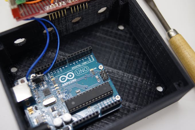
If you short-circuit the pin as shown in the picture, it will be recognized as normal Arduino.
If not (when not short-circuited), arduino UNO will be recognized as a MIDI device.
In other words, when writing code using the arduino IDE, you have to short-circuit the pins as shown in the picture.
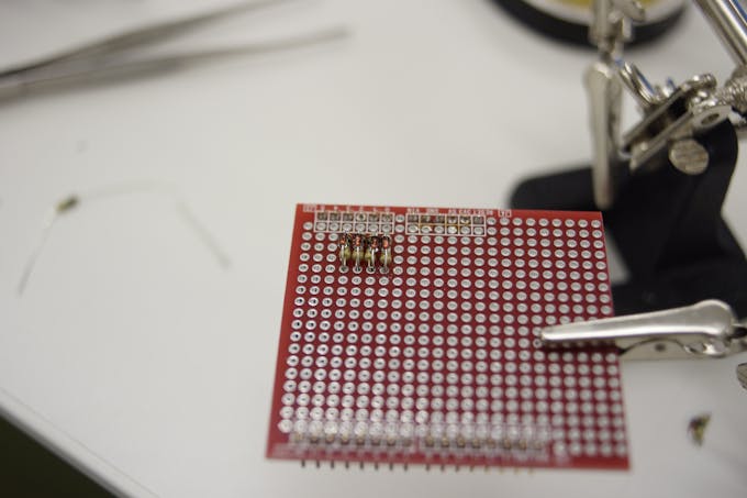
There is arduino UNO and shield in the box.
Refer to the image of fritzing for the circuit of the shield.
Diodes are for protection but I saw the information that arduino UNO has protection circuit, diodes may not be necessary. Does anyone know about this?
After printing the model of the case and the cover first, it is good to make the shield according to it.
There is also a 3D model of the cover, but I made a cover with a laser cutter. Please choose whichever you like.
Just start garageband and connect. There is no particularly difficult setting.
There are a number of DAWs for PCs that can be used on this drum set, including GarageBand.
Among them, Hydrogen is free and you can add sound.
Step 12 : SettingIn making the code, it was troublesome to rewrite the code each time the value changed, so I wanted to be able to change the value with arduino alone.
In other words, this is made for debugging code, so there are items that do not need to be changed.
Nevertheless, setting is necessary depending on the size of the piezo, the size of the pad, the hardness of the sponge foam.
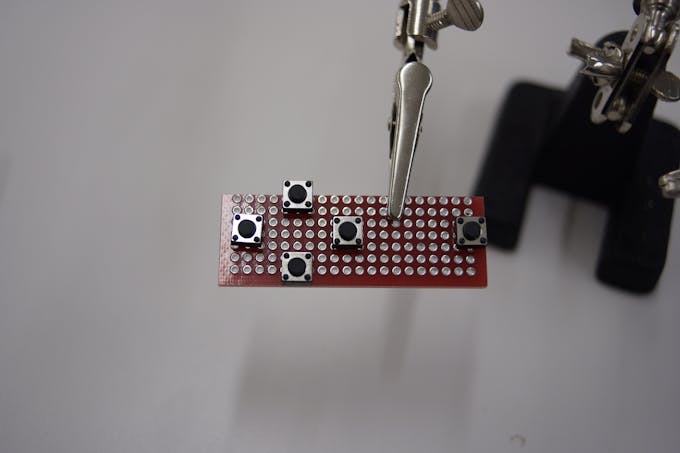
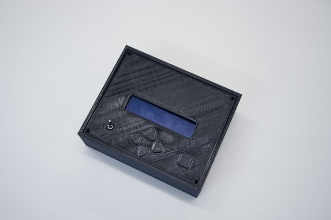
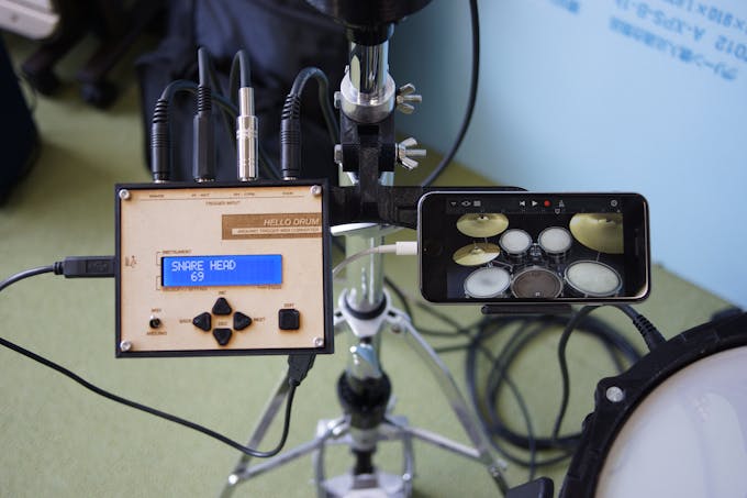
Select an instrument with the INC / DEC button and select the setting item with the NEXT / BACK button. When the EDIT button is pressed while the instruments and items you want to set are displayed, you can change the value with the INC / DEC button. Then, pressing the EDIT button again confirms the change.
If you watch at the latter part of the video you will understand how to operate.
THRESHOLD
The lowest value at which sound comes out
SENSITIVITY
Sensor sensitivity. If you lower it, you will gain high velocity even if you hit softly.
Number of the note. By changing, you can change instruments. Please refer to the image.
FLAG
A value for judging that the beating is over. You do not have to change it too much. It would be nice to set the value from 1 to 10. If you raise the value too much, you will get a sound twice with a single hit. If you lower it too much, you may get out of sound when you hit repeatedly.
SCAN TIME
In searching for peaks, values are taken consecutively for several milliseconds after exceeding the threshold. The highest value among them will peak. This several milliseconds is SCANTIME. There is no need to change it.
HEAD / RIM
Set the ease of the rim. Raising it makes it difficult to sound. If you lower it too hard the rim will sound when you hit the head. Regarding the judgment of the head and the rim, it may be necessary to improve the code
PEDAL VELO
Unlike other pads, the velocity of the pedal is constant. The initial value is 100. Please change to your favorite value.
MASK TIME
This is a value related to FLAG. There is no need to change it. If you raise it, you may not hear a sound when you hit continuously.
Some parts may not be usable unless their dimensions are changed. It is difficult to edit STL data. So I uploaded fusion 360 data. However, since I am editing data while trial and error, it is better not to depend too much on the history function.
https://github.com/RyoKosaka/drums/tree/master/Fusion360
EXTRAExtra steps are on instructables.
https://www.instructables.com/id/Arduino-Minimal-Drum-Kit/
And, detailed production process is published on this blog.
Check it if you are interested.
Please feel free to ask anything.
Have fun!
Hello Drum