Modbus (RS-485) Using Arduino © GPL3+
DESCRIPTION
RS-485 is one type of asynchronous serial communication protocol because there is no synchronizing clock signal transmitted along with the data. RS-485 uses differential signaling to transfer binary data from one device to another. Differential signaling worked by creating differential voltage using 5V positive and negative.This differential signaling method has the advantage in rejecting common mode noise.
RS-485 supports a maximum data transfer rate of 30 Mbps. RS-485 also supports many slaves with a single master. RS-485 protocol can have up to 32 devices connected.
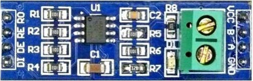
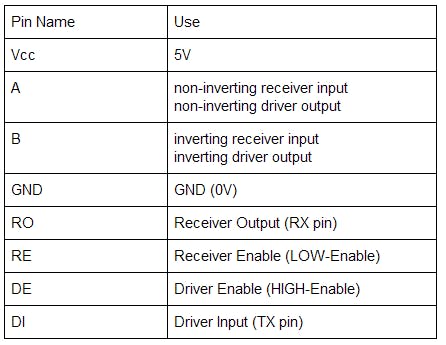
In this project, we are going to implement RS-485 protocol in communication between two Arduinos using MAX485 module. This module uses 5V as operating voltage and has pinout configuration as shown in the following table.
RS-485 module as transmitter
In order to be used as a transmitter, RE pin and DE pin must be connected to 5V, and DI pin is connected to TX. Data is sent from Arduino TX pin to module DI pin, then data will be sent through AB.
RS-485 module as receiver
In order to be used as a receiver, RE pin and DE pin must be connected to GND, and RO pin is connected to RX. Data received by AB will be sent to RO pin that is connected to Arduino RX pin so the data can be read by Arduino.
RS-485 can be implemented into three types of serial communication system: simplex, half-duplex, and full-duplex. But in this project, we are only implementing simplex and half-duplex.
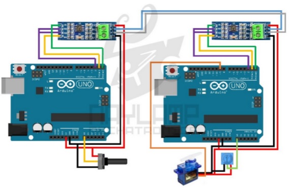
Simplex communication between two Arduinos by RS485
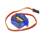
Simplex communication is unidirectional communication (one sends data and the other only receives data), with one arduino behaving only as transmitter and the other only as receivers. In this experiment, the transmitter reads data from potentiometer to control the servo motor which is connected to the receiver.
The result is as shown in video below:
Half-duplex communication between two Arduinos by RS485
Half-duplex communication is two-way communication using one channel which we cannot receive and transfer data at the same time. Both arduino behave either as transmitter or receiver alternately, controlled by a GPIO pin (HIGH to enable as transmitter, LOW to enable as receiver). In this experiment, Arduino 1 not only reads data from potentiometer to control the servo motor connected to Arduino 2, but also receives data from sensor (represented as potentiometer) connected to Arduino 2, then turns on the built-in LED if the data has reached the threshold.
The result is as shown in video below:
Reference:
https://naylampmechatronics.com/blog/37_Comunicación-RS485-con-Arduino.html

RS-485 is one type of asynchronous serial communication protocol because there is no synchronizing clock signal transmitted along with the data. RS-485 uses differential signaling to transfer binary data from one device to another. Differential signaling worked by creating differential voltage using 5V positive and negative.This differential signaling method has the advantage in rejecting common mode noise.
RS-485 supports a maximum data transfer rate of 30 Mbps. RS-485 also supports many slaves with a single master. RS-485 protocol can have up to 32 devices connected.
In this project, we are going to implement RS-485 protocol in communication between two Arduinos using MAX485 module. This module uses 5V as operating voltage and has pinout configuration as shown in the following table.
RS-485 module as transmitter
In order to be used as a transmitter, RE pin and DE pin must be connected to 5V, and DI pin is connected to TX. Data is sent from Arduino TX pin to module DI pin, then data will be sent through AB.
RS-485 module as receiver
In order to be used as a receiver, RE pin and DE pin must be connected to GND, and RO pin is connected to RX. Data received by AB will be sent to RO pin that is connected to Arduino RX pin so the data can be read by Arduino.
RS-485 can be implemented into three types of serial communication system: simplex, half-duplex, and full-duplex. But in this project, we are only implementing simplex and half-duplex.
Simplex communication between two Arduinos by RS485
Simplex communication is unidirectional communication (one sends data and the other only receives data), with one arduino behaving only as transmitter and the other only as receivers. In this experiment, the transmitter reads data from potentiometer to control the servo motor which is connected to the receiver.
The result is as shown in video below:
Half-duplex communication between two Arduinos by RS485
Half-duplex communication is two-way communication using one channel which we cannot receive and transfer data at the same time. Both arduino behave either as transmitter or receiver alternately, controlled by a GPIO pin (HIGH to enable as transmitter, LOW to enable as receiver). In this experiment, Arduino 1 not only reads data from potentiometer to control the servo motor connected to Arduino 2, but also receives data from sensor (represented as potentiometer) connected to Arduino 2, then turns on the built-in LED if the data has reached the threshold.
The result is as shown in video below:
Reference:
https://naylampmechatronics.com/blog/37_Comunicación-RS485-con-Arduino.html
MAX485 Module -> Arduino
Vcc -> 5V
GND -> GND
RO -> -
RE -> 5V
DE -> 5V
DI -> TX
Potentiometer -> Arduino
Vcc -> 5V
GND -> GND
Output -> A0
For receiver (Arduino 2)
MAX485 Module -> Arduino
Vcc -> 5V
GND -> GND
RO -> RX
RE -> GND
DE -> GND
DI -> -
Servo Motor -> Arduino
Vcc (Red) -> 5V
GND (Brown) -> GND
PWM (Orange) -> GPIO 9
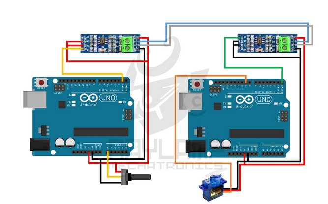
MAX485 Module -> Arduino
Vcc -> 5V
GND -> GND
RO -> RX
RE -> GPIO 2
DE -> GPIO 2
DI -> TX
For Arduino 1
Potentiometer -> Arduino
Vcc -> 5V
GND -> GND
Output -> A0
For Arduino 2:
Servo Motor -> Arduino
Vcc (Red) -> 5V
GND (Brown) -> GND
PWM (Orange) -> GPIO 9
Potentiometer -> Arduino (Arduino 2)
Vcc -> 5V
GND -> GND
Output -> A0
header + identifier + data value + footer
Receiver data frame
header + identifier + footer