Trybotics Logo

Music Reactive LED Strip

DESCRIPTION

My 14yo niece is getting into music, so I wanted to make her something cool for her room. I've also been interested in sound-reactive projects, so this was a good learning project.

Demo

Here's the demo on Youtube.

Introduction

This project was pretty simple and has been done countless times, but for me, it was fun to put together a bunch of pieces and to package it into a fun "end product".

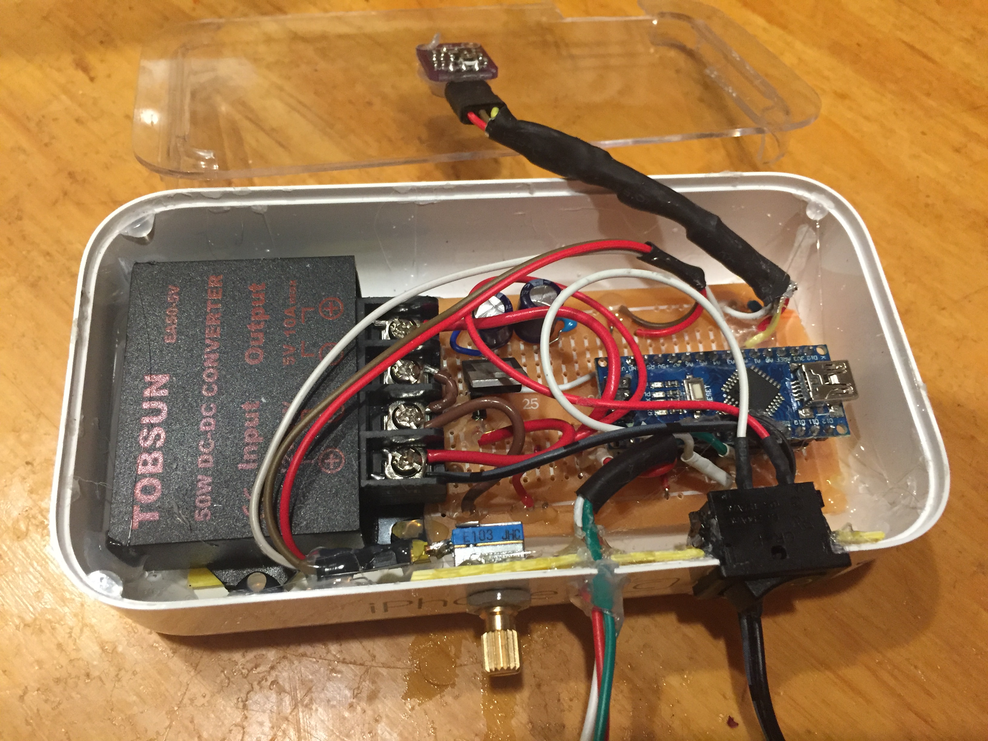
I used the Arduino Nano as the base. Used the FFT library to decode the sound into octaves, FASTLed library to drive the led strips, and an old iPhone C case to hold it all together.

A few notes about the software/features:

1) I use a 10kOhm POT to control the sound sensitivity

2) Microphone/amplifier is sensitive to noise, so I shielded the wires/leads with grounded metal tape...which helped a lot.

3) The strip responds in a few ways.

  • changes color/brightness/saturation based on volume of each octave
  • repeats the same 11 LED pattern across the strip (but morphs the colors and flip-flops each set so it looks more continuous
  • as it gets louder, the pattern chases along the strip
  • at the loudest, it strobes white briefly
  • you need to test out the pink noise to get it tuned correctly. this changes from board to board

4) I used an old 12V 1.5A Wall Wart as power supply. It's a little underpowered... but should be okay if she doesn't drive it so hard. I think a 24V 2A supply would be better. Also, I could have put in a larger capacitor (instead of the just the 470uF) at the power supply to the LED's. That would have helped with the current bursts. Next time...
Description:

09507 01
Soldering iron (generic)

Description:

Description:

My 14yo niece is getting into music, so I wanted to make her something cool for her room. I've also been interested in sound-reactive projects, so this was a good learning project.

Demo

Here's the demo on Youtube.

Introduction

This project was pretty simple and has been done countless times, but for me, it was fun to put together a bunch of pieces and to package it into a fun "end product".

I used the Arduino Nano as the base. Used the FFT library to decode the sound into octaves, FASTLed library to drive the led strips, and an old iPhone C case to hold it all together.

A few notes about the software/features:

1) I use a 10kOhm POT to control the sound sensitivity

2) Microphone/amplifier is sensitive to noise, so I shielded the wires/leads with grounded metal tape...which helped a lot.

3) The strip responds in a few ways.

  • changes color/brightness/saturation based on volume of each octave
  • repeats the same 11 LED pattern across the strip (but morphs the colors and flip-flops each set so it looks more continuous
  • as it gets louder, the pattern chases along the strip
  • at the loudest, it strobes white briefly
  • you need to test out the pink noise to get it tuned correctly. this changes from board to board

4) I used an old 12V 1.5A Wall Wart as power supply. It's a little underpowered... but should be okay if she doesn't drive it so hard. I think a 24V 2A supply would be better. Also, I could have put in a larger capacitor (instead of the just the 470uF) at the power supply to the LED's. That would have helped with the current bursts. Next time...

Description:

Music reactive LED stripArduino
Using Arduino IDE. Install FastLED and FFT libraries, then just run/upload to your Arduino (I used the same code on both Mega and Nano. This code is modified/copied from several other projects that you can find online.

NOTE that you can't disable the TIMER for FFT, because FASTLed requires the timer.
#include "FastLED.h"

// How many leds in your strip?
#include <FastLED.h>


#define OCTAVE 1 //   // Group buckets into octaves  (use the log output function LOG_OUT 1)
#define OCT_NORM 0 // Don't normalise octave intensities by number of bins
#define FHT_N 256 // set to 256 point fht
#include <FHT.h> // include the library
//int noise[] = {204,188,68,73,150,98,88,68}; // noise level determined by playing pink noise and seeing levels [trial and error]{204,188,68,73,150,98,88,68}


// int noise[] = {204,190,108,85,65,65,55,60}; // noise for mega adk
//int noise[] = {204,195,100,90,85,80,75,75}; // noise for NANO
int noise[] = {204,198,100,85,85,80,80,80};
float noise_fact[] = {15, 7, 1.5, 1, 1.2, 1.4, 1.7,3}; // noise level determined by playing pink noise and seeing levels [trial and error]{204,188,68,73,150,98,88,68}
float noise_fact_adj[] = {15, 7, 1.5, 1, 1.2, 1.4, 1.7,3}; // noise level determined by playing pink noise and seeing levels [trial and error]{204,188,68,73,150,98,88,68}


#define LED_PIN     5
#define LED_TYPE    WS2811
#define COLOR_ORDER GRB


// Params for width and height
const uint8_t kMatrixWidth = 11;
const uint8_t kMatrixHeight = 27;
 #define NUM_LEDS (kMatrixWidth * kMatrixHeight)
//#define NUM_LEDS    15

CRGB leds[NUM_LEDS];

int counter2=0;


void setup() { 
//  Serial.begin(115200);
  delay(1000);
  FastLED.addLeds<LED_TYPE, LED_PIN, COLOR_ORDER>(leds, NUM_LEDS).setCorrection( TypicalLEDStrip );
  
  FastLED.setBrightness (200);
  fill_solid(leds, NUM_LEDS, CRGB::Black); 
  FastLED.show();    
// TIMSK0 = 0; // turn off timer0 for lower jitter
  ADCSRA = 0xe5; // set the adc to free running mode
  ADMUX = 0x40; // use adc0
  DIDR0 = 0x01; // turn off the digital input for adc0

}


void loop() { 
int prev_j[8];
int beat=0;
int prev_oct_j;
int counter=0;
int prev_beat=0;
int led_index=0;
int saturation=0;
int saturation_prev=0;
int brightness=0;
int brightness_prev=0;

 while (1) { // reduces jitter

      cli();  // UDRE interrupt slows this way down on arduino1.0
     
  for (int i = 0 ; i < FHT_N ; i++) { // save 256 samples
      while (!(ADCSRA & 0x10)); // wait for adc to be ready
      ADCSRA = 0xf5; // restart adc
      byte m = ADCL; // fetch adc data
      byte j = ADCH;
      int k = (j << 8) | m; // form into an int
      k -= 0x0200; // form into a signed int
      k <<= 6; // form into a 16b signed int
      fht_input[i] = k; // put real data into bins
    }
    fht_window(); // window the data for better frequency response
    fht_reorder(); // reorder the data before doing the fht
    fht_run(); // process the data in the fht
    fht_mag_octave(); // take the output of the fht  fht_mag_log()

   // every 50th loop, adjust the volume accourding to the value on A2 (Pot)
    if (counter >= 50) {
      ADMUX = 0x40 | (1 & 0x07); // set admux to look at Analogpin A1 - Master Volume
 

      while (!(ADCSRA & 0x10)); // wait for adc to be ready
      ADCSRA = 0xf5; // restart adc 
  delay(10);      
      while (!(ADCSRA & 0x10)); // wait for adc to be ready
      ADCSRA = 0xf5; // restart adc 
      byte m = ADCL; // fetch adc data
      byte j = ADCH;
      int k = (j << 8) | m; // form into an int
      float master_volume=(k+0.1)/1000 +.5;  // so the valu will be between ~0.5 and 1.5
 // Serial.println (master_volume);


      for (int i=1; i<8; i++) {
          noise_fact_adj[i]=noise_fact[i]*master_volume;
      }

      ADMUX = 0x40 | (0 & 0x07); // set admux back to look at A0 analog pin (to read the microphone input
      counter = 0;
    }
        
    sei();
    counter++;
 
     
    // End of Fourier Transform code - output is stored in fht_oct_out[i].

    // i=0-7 frequency (octave) bins (don't use 0 or 1), fht_oct_out[1]= amplitude of frequency for bin 1
    // for loop a) removes background noise average and takes absolute value b) low / high pass filter as still very noisy
    // c) maps amplitude of octave to a colour between blue and red d) sets pixel colour to amplitude of each frequency (octave)
 
    for (int i = 1; i < 8; i++) {  // goes through each octave. skip the first 1, which is not useful

      int j;      
      j = (fht_oct_out[i] - noise[i]); // take the pink noise average level out, take the asbolute value to avoid negative numbers
      if (j<10) {j=0;}  
      j= j*noise_fact_adj[i];
       
      if (j<10) {j=0;}
      else {  
        j= j*noise_fact_adj[i];
        if (j>180) {
          if (i>=7) {
            beat+=2;
          }
          else {
            beat+=1;
          }
        }
        j=j/30;
        j=j*30; // (force it to more discrete values)
      }
      
      prev_j[i]=j;

//     Serial.print(j);
//     Serial.print(" "); 

 
// this fills in 11 LED's with interpolated values between each of the 8 OCT values 
       if (i>=2) {
        led_index=2*i-3;
        prev_oct_j=(j+prev_j[i-1])/2;
        
        saturation=constrain(j+30, 0,255);
        saturation_prev=constrain(prev_oct_j+30, 0,255);
        brightness=constrain(j, 0,255);
        brightness_prev=constrain(prev_oct_j, 0,255);
if (brightness==255) {
  saturation=50;
  brightness=200;
}
if (brightness_prev==255) {
  saturation_prev=50;
  brightness_prev=200;
}


        for (uint8_t y=0;y<kMatrixHeight;y++){  
          leds[XY(led_index-1,y)] = CHSV(j+y*30,saturation, brightness);        
          if (i>2){         
            prev_oct_j=(j+prev_j[i-1])/2;
            leds[ XY(led_index-2,y)]=CHSV(prev_oct_j+y*30,saturation_prev, brightness_prev);             
          }              
        }
       }
    }


      if (beat>=7) {
          fill_solid(leds, NUM_LEDS, CRGB::Gray);          
          FastLED.setBrightness(120);


 //    FastLED.setBrightness(200);

      }                 
    else {
      if (prev_beat!=beat) {
        FastLED.setBrightness(40+beat*beat*5);
        prev_beat=beat;
      }

    }

    FastLED.show(); 
    if (beat) {
      counter2+=((beat+4)/2-2);
      if (counter2<0) {counter2=1000;}
      if (beat>3 && beat<7) {
         FastLED.delay (20);
      }
      beat=0;
    }

// Serial.println();
 }
}


// Param for different pixel layouts
const bool    kMatrixSerpentineLayout = true;
// Set 'kMatrixSerpentineLayout' to false if your pixels are 
// laid out all running the same way, like this:

// Set 'kMatrixSerpentineLayout' to true if your pixels are 
// laid out back-and-forth, like this:

uint16_t XY( uint8_t x, uint8_t y)
{
  uint16_t i;
  
  if( kMatrixSerpentineLayout == false) {
    i = (y * kMatrixWidth) + x;
  }

  if( kMatrixSerpentineLayout == true) {
    if( y & 0x01) {
      // Odd rows run backwards
      uint8_t reverseX = (kMatrixWidth - 1) - x;
      i = (y * kMatrixWidth) + reverseX;

    } else {
      // Even rows run forwards
      i = (y * kMatrixWidth) + x;

    }
  }
  
  i=(i+counter2)%NUM_LEDS;  
  return i;
}

Description:

Schematic
Schematic tgkrlkh56p
Overview
There are only 3 parts. Wall Wart Power Supply, Enclosure, LED Strip
Img 3977 aa6vxsloia
Inside enclosure
I soldered everything only a Protoboard and hot-glued it all in an old iPhone C case. It was tight, but works!
Img 3982 3xyrj2mzib


YOU MIGHT ALSO LIKE