nRF24L01 Interfacing with Arduino | Wireless Communication
DESCRIPTION
In this tutorial, you will learn about nRF24L01 Arduino interfacing with the help of two examples. In the first example, we will send “Hello world” and a command to blink the LED connected to the other Arduino. In the second example, we will do the bidirectional control and will send the command from First Arduino to blink the LED on the second and then we will send the command from second Arduino to blink the LED on the first.
For Custom Projects, hire me at https://www.freelancer.com/u/Muhammadaqibdutt
Before going in detail, first have a look at the specification of this module
nRF24L01 Module
The nFR24L01 is a transceiver module which means that it can both send and receive the data.
These modules are very cheap, smaller in size and has a lot of specifications. Some of the specifications of these modules are as follows
Specifications of nRF24L01 Module
- Power consumption is around 12mA during transmission which is even lesser than the led.
- It can operate with baud rates from 250Kbps up to 2 Mbps.
- Its range can reach up to 100 meters if used in open space and with antenna.
- It can both send and receive the data simultaneously.
- Each module can communicate with up to 6 other modules.
- It uses the 2.4 GHz band.
- It can send 1 to 25 bytes of raw data at the transmission rate of 1 MB.
- It has 125 different channels.
Pinout
The nRF24L01 module works with the Arduino through the SPI communication. The pinout of the module is as follows

The operating voltage of this module is from 1.9 to 3.6V but the other pins are 5V tolerant which means that the other pins can be directly connected to the Arduino.
The MOSI, MISO and the SCK are the SPI pins and these needs to be connected to the SPI pins of Arduino. Different Arduino’s have different SPI pins.
The CSN and CE are for setting the module in active mode and for switching between command and transmit mode. These can be connected to any digital pins of Arduino.
The IRQ pin is the interrupt pin and you don’t have to connect it.
Example 1 - nRF24L01 Arduino Interfacing
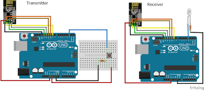
In the first example for nRF24L01 arduino interfacing, we are going to simply send the data from one Arduino to other Arduino. When we will press the button connected to the first Arduino, LED connected to the second Arduino will light up.
The circuit diagram for the first example is shown below and the connections are shown below that.
Code for Transmitter
Download the library from here.
#include <SPI.h>
#include <nRF24L01.h>
#include <RF24.h>
RF24 radio(9, 10); // CE, CSN
const byte address[6] = "00001"; //Byte of array representing the address. This is the address where we will send the data. This should be same on the receiving side.
int button_pin = 2;
boolean button_state = 0;
void setup() {
pinMode(button_pin, INPUT);
radio.begin(); //Starting the Wireless communication
radio.openWritingPipe(address); //Setting the address where we will send the data
radio.setPALevel(RF24_PA_MIN); //You can set it as minimum or maximum depending on the distance between the transmitter and receiver.
radio.stopListening(); //This sets the module as transmitter
}
void loop()
{
button_state = digitalRead(button_pin);
if(button_state == HIGH)
{
const char text[] = "Your Button State is HIGH";
radio.write(&text, sizeof(text)); //Sending the message to receiver
}
else
{
const char text[] = "Your Button State is LOW";
radio.write(&text, sizeof(text)); //Sending the message to receiver
}
radio.write(&button_state, sizeof(button_state)); //Sending the message to receiver
delay(1000);
}
Code for Receiver
#include <SPI.h>
#include <nRF24L01.h>
#include <RF24.h>
RF24 radio(9, 10); // CE, CSN
const byte address[6] = "00001";
boolean button_state = 0;
int led_pin = 3;
void setup() {
pinMode(6, OUTPUT);
Serial.begin(9600);
radio.begin();
radio.openReadingPipe(0, address); //Setting the address at which we will receive the data
radio.setPALevel(RF24_PA_MIN); //You can set this as minimum or maximum depending on the distance between the transmitter and receiver.
radio.startListening(); //This sets the module as receiver
}
void loop()
{
if (radio.available()) //Looking for the data.
{
char text[32] = ""; //Saving the incoming data
radio.read(&text, sizeof(text)); //Reading the data
radio.read(&button_state, sizeof(button_state)); //Reading the data
if(button_state == HIGH)
{
digitalWrite(6, HIGH);
Serial.println(text);
}
else
{
digitalWrite(6, LOW);
Serial.println(text);}
}
delay(5);
}
Video
Example 2 - nRF24L01 Arduino Interfacing
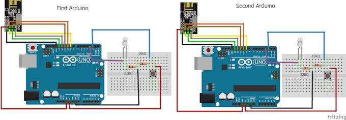
In the second example for nRF24L01 Arduino interfacing, we are going to do the bidirectional communication. First, we will send the command from the first Arduino to light up the LED connected to the second Arduino and then we will send the command from the second Arduino to light up the LED connected to the first Arduino.
Code for First Arduino
#include <SPI.h>
#include <nRF24L01.h>
#include <RF24.h>
RF24 radio(9, 10); // CE, CSN
const byte addresses [][6] = {"00001", "00002"}; //Setting the two addresses. One for transmitting and one for receiving
int button_pin = 2;
int led_pin = 3;
boolean button_state = 0;
boolean button_state1 = 0;
void setup() {
 pinMode(button_pin, INPUT);
 pinMode(led_pin, OUTPUT);
 radio.begin(); //Starting the radio communication
 radio.openWritingPipe(addresses[1]); //Setting the address at which we will send the data
 radio.openReadingPipe(1, addresses[0]); //Setting the address at which we will receive the data
 radio.setPALevel(RF24_PA_MIN); //You can set it as minimum or maximum depending on the distance between the transmitter and receiver.
}
void loop()
{
 delay(5);
 radio.stopListening(); //This sets the module as transmitter
 button_state = digitalRead(button_pin);
 radio.write(&button_state, sizeof(button_state)); //Sending the data
 delay(5);

 radio.startListening(); //This sets the module as receiver
 while(!radio.available()); //Looking for incoming data
 radio.read(&button_state1, sizeof(button_state1)); //Reading the data
 if (button_state1 == HIGH)
 {
 digitalWrite(led_pin, HIGH);
 }
 else
 {
 digitalWrite(led_pin, LOW);
 }
}
Code for Second Arduino
#include <SPI.h>
#include <nRF24L01.h>
#include <RF24.h>
RF24 radio(9, 10); // CE, CSN
const byte addresses [][6] = {"00001", "00002"}; //Setting the two addresses. One for transmitting and one for receiving
int button_pin = 2;
boolean button_state = 0;
boolean button_state1 = 0;
int led_pin = 3;
void setup() {
 pinMode(led_pin, OUTPUT);
 Serial.begin(9600);
 radio.begin(); //Starting the radio communication
 radio.openWritingPipe(addresses[0]); //Setting the address at which we will send the data
 radio.openReadingPipe(1, addresses[1]); //Setting the address at which we will receive the data
 radio.setPALevel(RF24_PA_MIN); //You can set it as minimum or maximum depending on the distance between the transmitter and receiver.
}
void loop()
{
 delay(5);
 radio.startListening(); //This sets the module as receiver
 if (radio.available()) //Looking for incoming data
 {
 radio.read(&button_state, sizeof(button_state));
 if(button_state == HIGH)
 {
 digitalWrite(led_pin, HIGH);
 }
 else
 {
 digitalWrite(led_pin, LOW);
 }
 delay(5);

 radio.stopListening(); //This sets the module as transmitter
 button_state1 = digitalRead(button_pin);
 radio.write(&button_state1, sizeof(button_state1)); //Sending the data
 }
}
Video

In this tutorial, you will learn about nRF24L01 Arduino interfacing with the help of two examples. In the first example, we will send “Hello world” and a command to blink the LED connected to the other Arduino. In the second example, we will do the bidirectional control and will send the command from First Arduino to blink the LED on the second and then we will send the command from second Arduino to blink the LED on the first.
For Custom Projects, hire me at https://www.freelancer.com/u/Muhammadaqibdutt
Before going in detail, first have a look at the specification of this module
nRF24L01 Module
The nFR24L01 is a transceiver module which means that it can both send and receive the data.
These modules are very cheap, smaller in size and has a lot of specifications. Some of the specifications of these modules are as follows
Specifications of nRF24L01 Module
- Power consumption is around 12mA during transmission which is even lesser than the led.
- It can operate with baud rates from 250Kbps up to 2 Mbps.
- Its range can reach up to 100 meters if used in open space and with antenna.
- It can both send and receive the data simultaneously.
- Each module can communicate with up to 6 other modules.
- It uses the 2.4 GHz band.
- It can send 1 to 25 bytes of raw data at the transmission rate of 1 MB.
- It has 125 different channels.
Pinout
The nRF24L01 module works with the Arduino through the SPI communication. The pinout of the module is as follows
The operating voltage of this module is from 1.9 to 3.6V but the other pins are 5V tolerant which means that the other pins can be directly connected to the Arduino.
The MOSI, MISO and the SCK are the SPI pins and these needs to be connected to the SPI pins of Arduino. Different Arduino’s have different SPI pins.
The CSN and CE are for setting the module in active mode and for switching between command and transmit mode. These can be connected to any digital pins of Arduino.
The IRQ pin is the interrupt pin and you don’t have to connect it.
Example 1 - nRF24L01 Arduino Interfacing
In the first example for nRF24L01 arduino interfacing, we are going to simply send the data from one Arduino to other Arduino. When we will press the button connected to the first Arduino, LED connected to the second Arduino will light up.
The circuit diagram for the first example is shown below and the connections are shown below that.
Code for Transmitter
Download the library from here.
#include <SPI.h>
#include <nRF24L01.h>
#include <RF24.h>
RF24 radio(9, 10); // CE, CSN
const byte address[6] = "00001";     //Byte of array representing the address. This is the address where we will send the data. This should be same on the receiving side.
int button_pin = 2;
boolean button_state = 0;
void setup() {
pinMode(button_pin, INPUT);
radio.begin();                  //Starting the Wireless communication
radio.openWritingPipe(address); //Setting the address where we will send the data
radio.setPALevel(RF24_PA_MIN);  //You can set it as minimum or maximum depending on the distance between the transmitter and receiver.
radio.stopListening();          //This sets the module as transmitter
}
void loop()
{
button_state = digitalRead(button_pin);
if(button_state == HIGH)
{
const char text[] = "Your Button State is HIGH";
radio.write(&text, sizeof(text));                  //Sending the message to receiver
}
else
{
const char text[] = "Your Button State is LOW";
radio.write(&text, sizeof(text));                  //Sending the message to receiver
}
radio.write(&button_state, sizeof(button_state));  //Sending the message to receiver
delay(1000);
}
Code for Receiver
#include <SPI.h>
#include <nRF24L01.h>
#include <RF24.h>
RF24 radio(9, 10); // CE, CSN
const byte address[6] = "00001";
boolean button_state = 0;
int led_pin = 3;
void setup() {
pinMode(6, OUTPUT);
Serial.begin(9600);
radio.begin();
radio.openReadingPipe(0, address);   //Setting the address at which we will receive the data
radio.setPALevel(RF24_PA_MIN);       //You can set this as minimum or maximum depending on the distance between the transmitter and receiver.
radio.startListening();              //This sets the module as receiver
}
void loop()
{
if (radio.available())              //Looking for the data.
{
char text[32] = "";                 //Saving the incoming data
radio.read(&text, sizeof(text));    //Reading the data
radio.read(&button_state, sizeof(button_state));    //Reading the data
if(button_state == HIGH)
{
digitalWrite(6, HIGH);
Serial.println(text);
}
else
{
digitalWrite(6, LOW);
Serial.println(text);}
}
delay(5);
}
Video
Example 2 - nRF24L01 Arduino Interfacing
In the second example for nRF24L01 Arduino interfacing, we are going to do the bidirectional communication. First, we will send the command from the first Arduino to light up the LED connected to the second Arduino and then we will send the command from the second Arduino to light up the LED connected to the first Arduino.
Code for First Arduino
#include <SPI.h>
#include <nRF24L01.h>
#include <RF24.h>
RF24 radio(9, 10); // CE, CSN
const byte addresses [][6] = {"00001", "00002"};  //Setting the two addresses. One for transmitting and one for receiving
int button_pin = 2;
int led_pin = 3;
boolean button_state = 0;
boolean button_state1 = 0;
void setup() {
  pinMode(button_pin, INPUT);
  pinMode(led_pin, OUTPUT);
  radio.begin();                           //Starting the radio communication
  radio.openWritingPipe(addresses[1]);     //Setting the address at which we will send the data
  radio.openReadingPipe(1, addresses[0]);  //Setting the address at which we will receive the data
  radio.setPALevel(RF24_PA_MIN); //You can set it as minimum or maximum depending on the distance between the transmitter and receiver.
}
void loop()
{
  delay(5);
  radio.stopListening();                             //This sets the module as transmitter
  button_state = digitalRead(button_pin);
  radio.write(&button_state, sizeof(button_state));  //Sending the data
  delay(5);

  radio.startListening();                            //This sets the module as receiver
  while(!radio.available());                         //Looking for incoming data
  radio.read(&button_state1, sizeof(button_state1)); //Reading the data
  if (button_state1 == HIGH)
  {
    digitalWrite(led_pin, HIGH);
  }
  else
  {
    digitalWrite(led_pin, LOW);
  }
}
Code for Second Arduino
#include <SPI.h>
#include <nRF24L01.h>
#include <RF24.h>
RF24 radio(9, 10); // CE, CSN
const byte addresses [][6] = {"00001", "00002"};    //Setting the two addresses. One for transmitting and one for receiving
int button_pin = 2;
boolean button_state = 0;
boolean button_state1 = 0;
int led_pin = 3;
void setup() {
  pinMode(led_pin, OUTPUT);
  Serial.begin(9600);
  radio.begin();                            //Starting the radio communication
  radio.openWritingPipe(addresses[0]);      //Setting the address at which we will send the data
  radio.openReadingPipe(1, addresses[1]);   //Setting the address at which we will receive the data
  radio.setPALevel(RF24_PA_MIN);            //You can set it as minimum or maximum depending on the distance between the transmitter and receiver.
}
void loop()
{
  delay(5);
  radio.startListening();                    //This sets the module as receiver
  if (radio.available())                     //Looking for incoming data
  {
    radio.read(&button_state, sizeof(button_state));
    if(button_state == HIGH)
  {
     digitalWrite(led_pin, HIGH);
  }
  else
  {
     digitalWrite(led_pin, LOW);
  }
  delay(5);

  radio.stopListening();                           //This sets the module as transmitter
  button_state1 = digitalRead(button_pin);
  radio.write(&button_state1, sizeof(button_state1));   //Sending the data
  }
}
Video
NRF24l01 Library

