Trybotics Logo

Obd2 Tachometer

DESCRIPTION

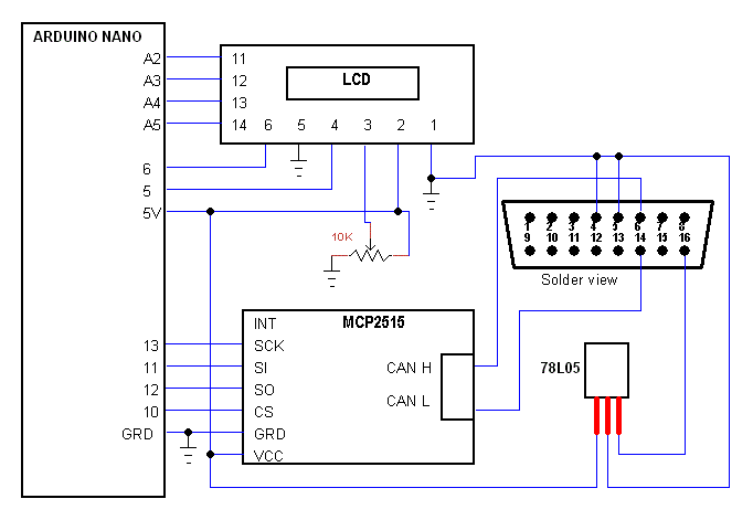
This project is good for cars with OBD2 protocol ISO 15765 11 bits 500 Kb/s, most European car has this protocol. The application reads data of the ECU using CAN. the MCP2515 module drives the CAN BUS.

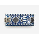
The circuit supply is from the car 12V and a 78L05 regulator that supply the Arduino and the CAN module. It is preferred to take the 12V from a connection that switches off when the engine is off, you can take 12V from the plug and add a switch. You need also a ground connection to the car ground.

For compiling the code you need to install a lib from GitHub. I left the debugging in the code for help in adding features. The code requests the data twice every second. The request is an address 7DF, number of bytes, service #, PID and padding 5 bytes of 0x55. The reply from the ECU is address 7E8, number of bytes, 0x41, PID, 2 bytes of data. The data is calculated byte1*256+byte2/4.
Description:

09507 01
Soldering iron (generic)

Description:

This project is good for cars with OBD2 protocol ISO 15765 11 bits 500 Kb/s, most European car has this protocol. The application reads data of the ECU using CAN. the MCP2515 module drives the CAN BUS.

The circuit supply is from the car 12V and a 78L05 regulator that supply the Arduino and the CAN module. It is preferred to take the 12V from a connection that switches off when the engine is off, you can take 12V from the plug and add a switch. You need also a ground connection to the car ground.

For compiling the code you need to install a lib from GitHub. I left the debugging in the code for help in adding features. The code requests the data twice every second. The request is an address 7DF, number of bytes, service #, PID and padding 5 bytes of 0x55. The reply from the ECU is address 7E8, number of bytes, 0x41, PID, 2 bytes of data. The data is calculated byte1*256+byte2/4.

Description:

obd2_tachoArduino
/* OBD2 TACHO
 * By moty22.co.uk 
 * Lib written By: Cory J. Fowler  December 20th, 2016
 * https://github.com/coryjfowler/MCP_CAN_lib 
 */ 

#include <mcp_can.h>
#include <SPI.h>
#include <LiquidCrystal.h>
#define standard 1  //standard is 11 bits
#define txID 0x7DF  //0x7E9

// initialize the lcd with the numbers of the interface pins
 LiquidCrystal lcd(5, 6, A2, A3, A4, A5);

unsigned long rxId;
byte len;
byte rxBuf[8];

unsigned char txData[8] = {0x02, 0x01, 0x0C, 0x55, 0x55, 0x55, 0x55, 0x55}; //PID to request 010C

MCP_CAN CAN0(10);                                // Set CAN0 CS to pin 10

void setup()
{
  Serial.begin(115200);
  while(!Serial);
  lcd.begin(16, 2);   // set up the LCD's number of columns and rows:  
  lcd.setCursor(3, 1);
  lcd.print("TACHOMETER");

  // Initialize MCP2515 running at baudrate of 500kb/s . If your can board has 16MHz crystal change the setting.  
  if(CAN0.begin(MCP_STDEXT, CAN_500KBPS, MCP_8MHZ) == CAN_OK)
    Serial.println("Initialized Successfully!");
  else
    Serial.println("**Error Initializing**");
  
  CAN0.setMode(MCP_NORMAL);                          // Set operation mode to normal so the MCP2515 sends acks to received data.

}

void loop()
{
  byte back=0;
  unsigned int rpm=100;
  
    delay(500);
    CAN0.sendMsgBuf(txID, 8, txData); //request data from ECU

    for(byte i=0;i<20;++i){       //get 20 times unless reply arrived from the ECU 
    CAN0.readMsgBuf(&rxId, &len, rxBuf);     // Get CAN data - 03 41 0C 3D 0F
     if(rxId == 0x7E8){
        Serial.print(rxId, HEX);  //0x7E8 
        Serial.print("\t");
        for(byte i = 0; i<len; i++)    // print the data
        {
            Serial.print(rxBuf[i], HEX);
            Serial.print("\t");            
        }
        Serial.println();
        back=1;

    }
    if(back){
      rpm = (rxBuf[3]*256 + rxBuf[4])/4;  //calculate the rpm
      Serial.println(rpm);
  
     lcd.clear();
     lcd.setCursor(5, 0); // top line
     lcd.print(rpm);
     lcd.setCursor(11, 0);
     lcd.print("rpm");
     lcd.setCursor(3, 1);
     lcd.print("TACHOMETER"); 
     break;
    }
  }
}

Description:

YOU MIGHT ALSO LIKE