Portable CoVID-19 clinic © CERN-OHL
DESCRIPTION
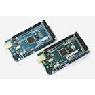
.Coming from India, I realized that the SARS-CoV-2 virus could've been scanned, detected, and treated easily before becoming a full-blown pandemic. My idea is versatile, easy-to-assemble, and does much more than clean masks. It also sanitizes your hands with an automatic sanitization machine that relies on the power of Arduino and ARM platforms. It may be a bit challenging to make, but each one can detect and diagnose body vitals, thus offsetting the cost of making and deploying them. It uses the coding of C++ (Arduino IDE) to make the sanitation suite come to life. This project uses an Arduino Or Genuino Mega 2560.
Bill of materials
About USD $300 (AED 850.
Orientation video
https://youtu.be/Xmy4RtmoXII
Resources needed on the ground
Assuming that the project is placed in a populated and high risk community, the resources needed are-
Electricity output of 15VDC or 12VDC if running on a power supply, else just buy a power bank with 2 5V usb outputs and plug those into the Arduino USB and the hub USB.
Liquid disinfectant (Dettol or watered down soap solution) for the water atomiser and the hand sanitiser
Internal medicine doctor or cardiologist or even a nurse (to monitor and diagnose MAXREFDES100's readings)
Android phone (for Maxim Apk app) OR PC (Windows only) and the PC is recommended for detailed diagnosis using oximetry as the Android app doesn’t display SpO2 levels.
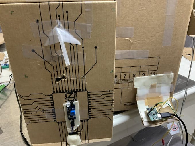
Structural Setup
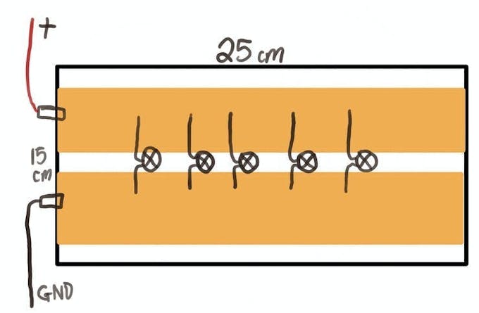
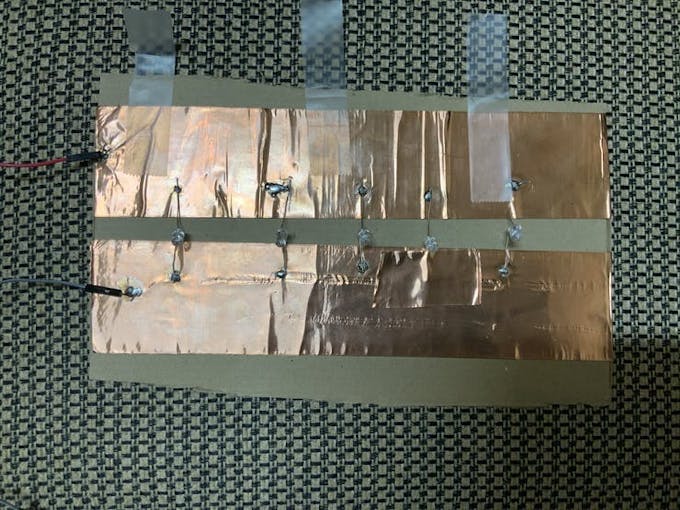
Structural SetupCut 2x 10 cm by 25 cm cardboard sheets and line 2 strips of copper tape parallel to each other: one strip for the positive terminal (+) and one for ground (GND) And then solder 5 UV LEDs for each copper-cardboard fixture shown below.
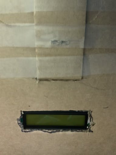
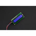
Then, cut a rectangular hole- wide enough for the 16 x 2 I2C LCD to fit into.
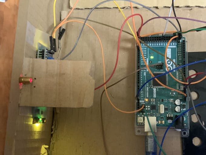
ArduinoHardwareHookup
These connections only work if you’ve already soldered the UV-C bulbs on the copper-cardboard fixture mentioned somewhere above.
The connections are as follows:
I2C 16X2 LCD
I2C 16X2 LCDSCL- Pin 21
SDA- Pin 20
VCC- 5V (on the power section)
GND- GND (on the power section)
Copper-cardboard fixtures
Copper-cardboard fixturesGround wires to both the grounds at the end of the digital pin column
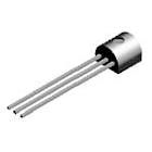
Jumper wire from pin 50 and 52 to the bases of both BC557 PNP transistors
Positive pin of copper-cardboard fixtures to the collectors of both BC557s
GND pins of fixtures to GND pin of breadboard rail (which also has a GND pin connected to the Mega)
Both emitter pins to 5V pin on the Mega 2560
Water Atomiser
VCC to 5V pin (which can be used to supply shields with 3.3V or 5V)
GND pin to the same ground rail as the LED strips.
EN pin to digital pin 40
Important: Only tape one of the copper-cardboard bulb fixtures for now. We need to tape the other one later after we have added the cardboard supports (strips which ensure structural integrity is maximum even if a heavy mask is dropped on the base).
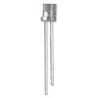
Laserdiode
VCC (Red wire) --> 5V
GND (Blue wire) --> GND
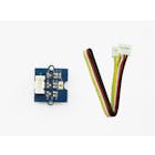
3-pin light sensor
3-pin light sensorVCC --> 3.3V
GND --> GND
OUT (Signal) --> D48
Adjust the frequency (blue potentiometer) of the light sensor using a screwdriver until it turns off exactly when the laser is covered, and on when it is exposed to the laser.
ArduinoCodeSetup
#include <Wire.h>
#include <LiquidCrystal_I2C.h>

LiquidCrystal_I2C lcd(0x27,16,2);

void setup()
{
 pinMode(48,INPUT); //D48 is the digital light sensor
lcd.init();
lcd.noCursor();
lcd.backlight();
pinMode(50, OUTPUT);
pinMode(52,OUTPUT);
pinMode(40, OUTPUT);
lcd.backlight();
lcd.display();
lcd.clear();

}


void loop()
{

 if (digitalRead(48)) {
 delay(1000);
 lcd.clear();
 lcd.print(String("Lower the lid"));
 delay(500);
 lcd.clear();
 lcd.print(String("Wait 30 mins"));
 digitalWrite(50,LOW);
 digitalWrite(52,LOW);
 digitalWrite(40,HIGH); //D40 is the water atomiser
 delay(1800000);
 digitalWrite(50,HIGH);
 digitalWrite(52,HIGH);
 digitalWrite(40,LOW);
 lcd.clear();
 lcd.print(String("Remove the mask!"));

 } else {
 digitalWrite(50,LOW);
 digitalWrite(40,LOW);
 lcd.setCursor(0, 0);
 lcd.print(String("Please place"));
 lcd.setCursor(0, 1);
 lcd.print(String("a mask in!"));

 }

}
Autohandsanitizer
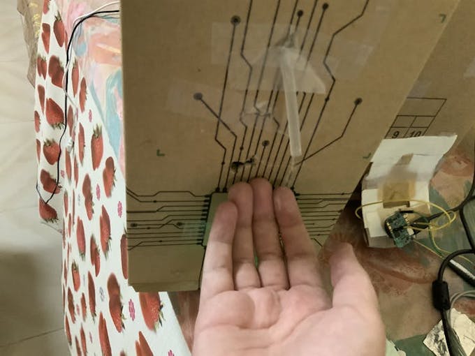
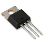
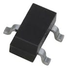
This addition to the project is crucial as it provides people one stop to clean masks and sanitise their hands. This sanitiser relies on an IR sensor (ultrasonic sensor requires much more code which is time consuming) and a 5V 500 mA peristaltic pump from Adafruit and works without a microcontroller which saves time and a lot of money. It relies on a TIP42C PNP transistor, to turn on the pump when the IR sensor detects an object nearby.
Transistor Base to IR sensor OUT
Collector to positive of motor
Emitter to positive of breadboard rail
IR sensor VCC to breadboard positive rail
IR sensor GND to breadboard negative (ground) rail
Add an image
Delete this image
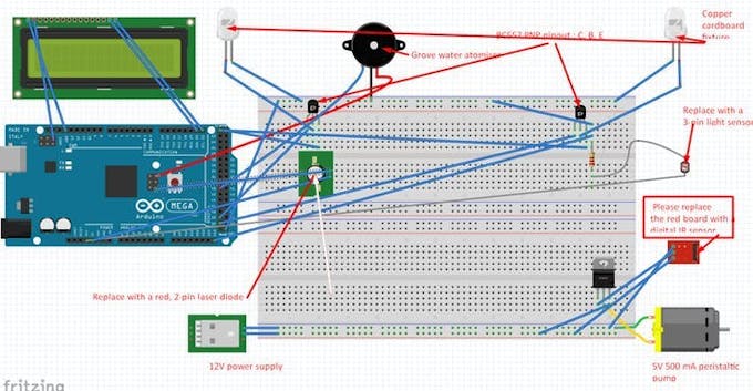
Disclaimer: I would strongly recommend that you rely on the wiring setup instruction in words, not the picture above. Fritzing is old and depreciated but I had no choice but to use it. The arrangement for different kinds of PNP transistors vary depending on the PNP model type. Here are the universal connections for PNP transistors in my project. I apologize if this causes any kind of trouble.
MAXREFDES100(MAX32620HSP) Software Setup
Note (MAXREFDES100 Setup)
Note (MAXREFDES100 Setup)Now, I know what you all are thinking: It's pretty expensive to be classified as a low-cost solution. However, the distribution of the machines should be trilaterally placed, meaning 3 of them should be placed at points in different villages, towns, etc. such that they are easily accessible by people in ambulances. Let's take Africa as an example: There are 22 underdeveloped nations (underdeveloped meaning no monitoring and diagnosis tools present in the entire area of the nation) in Africa, and we will take the biggest landmass and the biggest population. So Congo is the largest underdeveloped nation at a landmass of about 2, 344, 858 sq km (905, 355 sq mi), and Nigeria has the most population of about 200 million individuals as of December 2019. So the machines need to be placed at an average distance of 3 km away from each other. This is because African people walk on average about 4 km a day to collect water from wells, so they can walk that distance or be carried in an ambulance to the medical camp. These machines can also be rented by different ambulances with different time slots registered, with an extra 3 to 4 in place for emergencies. This device also contains defibrillation protection and can measure SpO2 concentration (blood oxygen level), BPM, body temperature and ECG readings, as well as with different LEDs, and environmental pressure to see if strain occurs because of heat, which an amateur cardiologist can read to determine whether the person has an underlying condition, and help to pre-emptively send the person for a CoVID-19 test (RT-PCR or UAE's new laser test) or to send them to a hospital to be treated for any signs of flu, or any disease that is directly linked to respiratory and cardiological damage. Thus, the cost of one machine offsets about 10 peoples worth of CoVID-19 critical stage treatment. In other words, helping to diagnose CoVID-19 in its primary stage or any other underlying condition that non-CoVID-19 sufferers are usually neglected or delayed treatment for is heavily relied on by using my machine
Now onto the actual setup:
I will only discuss how to set the HSP board up on the GUI and Android app. For more detail on how to set it up, please refer to the MAXREFDES100's product page. This is preferred or if you aren’t a visual learner: click on this video for setup instructions.
Hardware and Software Setup
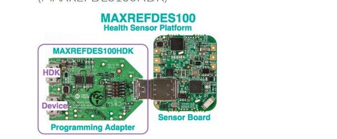
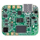
Insert the USB-C port of the HDK adapter into the HSP's port, and insert a micro-USB cable into the HDK port of the adapter and insert the other end into your computer.
Add an image
Delete this image
Press the only button on the sensor board for half a second and wait till the red LED lights up.
Then, on your PC, you should see a notification pop up, saying that COM10's setup is complete. (This allows us to upload custom firmware for the board if you want to later.)
Go to Device Manager and click on COM Ports (LPT) and check if the COM port exists.
Then, unplug the HDK adapter from your PC and simply plug a USB-C cable from the sensor board to the computer to set it up with the GUI
Then wait for a few minutes until a notification pops up saying "USB Serial Device (COM11) is set up)
Then, click this link to download the GUI or check it out on the product page.
After downloading the GUI for the first time, a window displaying UART configuration pops up beginning with a baud rate of 9600. Simply click Scan Ports to find COM11 (or whichever COM port the USB serial device is on) and then click Connect.
Then this page should pop up
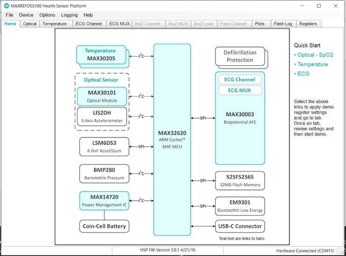
Click on the Optical tab and place your thumb or finger on the slightly large glass window with a red LED flashing on it.
Then click Start Monitor
Some readings should pop up 👆
Click the ECG MUX and select ECG OPENP and OPEN-N and select Connected.
Then enable EN_ECG and EN_RTOR (ECG and R-R if MAX30003 register names are disabled)
Then click on the Plots tab and select start monitor.
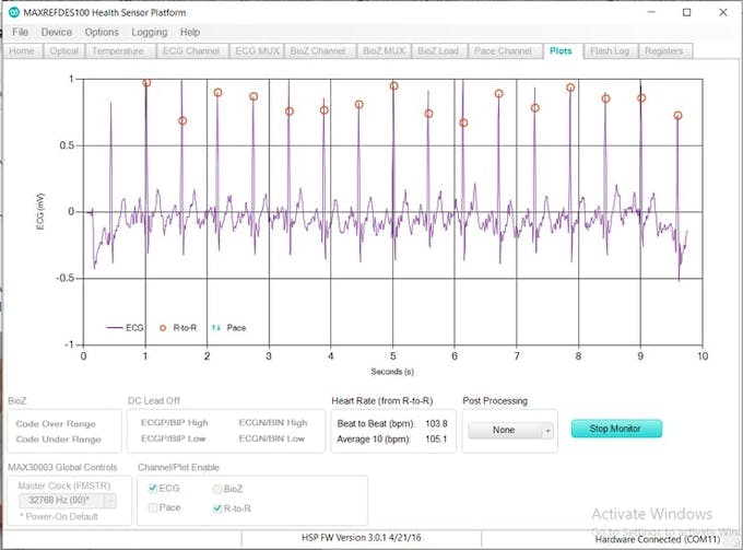
An ECG pulse should be showing up, provided the cables are soldered onto the board or pushed in using male header pins of jumper wires as well.
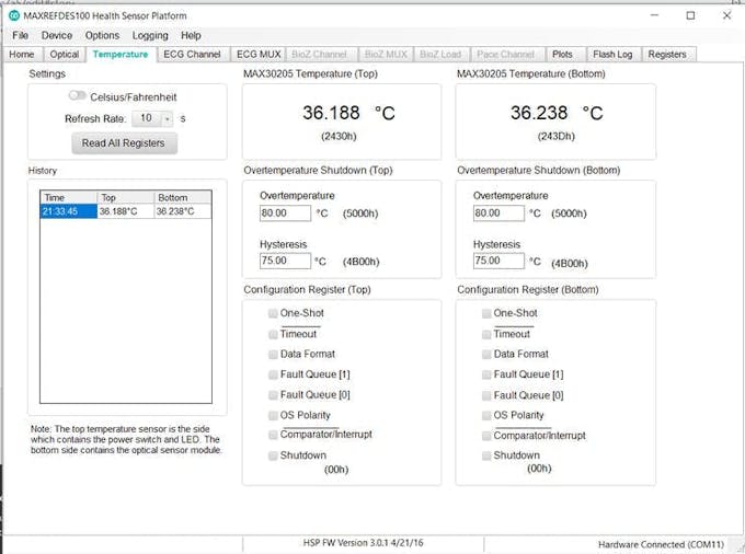
Click Temperature and blow on the sensor board. The temp. sensor readings should then rise.
That's all for the PC app.
Now let's move over to the Android app.
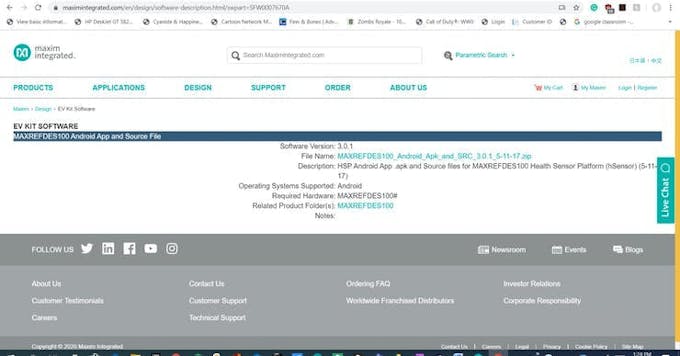
https://www.maximintegrated.com/en/design/software-description.html/swpart=SFW0007670A
Then click the file name and download the.zip folder
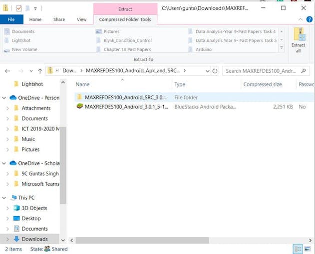
Click on the.apk file and copy it to your Google Drive (BlueStacks in the above picture).
Then, jump on to your Android phone and open the.apk file on Google Drive.
Download the.apk file and a page should pop up which scans for BLE ports
MAXREFDES100 should pop up under the list of available devices.
Then, tap the MAXREFDES100
Then, another page should pop up indicating the values of different sensors.
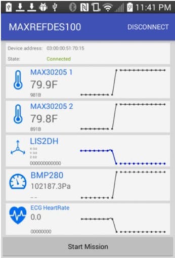
However, the optical sensor measurements and SpO2 levels are not indicated on this. Only, Windows PCs can show the temperature, ECG, and SpO2 levels necessary for patient monitoring. In this case, each location where the machine is placed should have a nearby PC with the GUI installed or simply for ECG measurement, a phone can be used to measure the effects of the environmental conditions on the person's state of health.
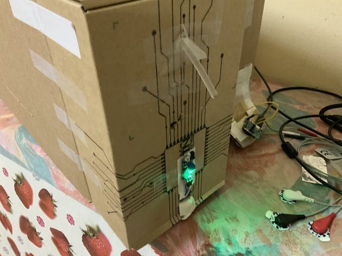
Structural Setup
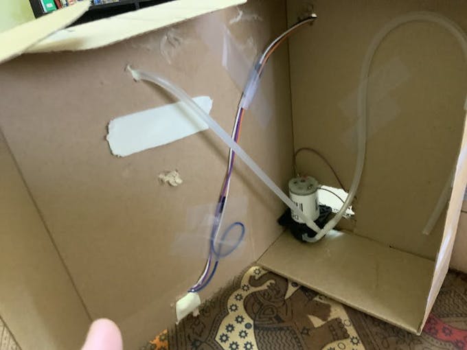
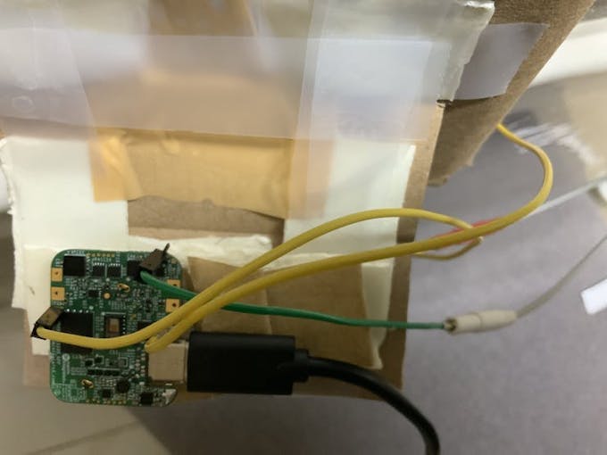
Place the MAXREFDES100 sensor board into a nice cardboard enclosure, like a tiny cardboard box that exposes the top part of the board which is the part containing the blood oxygen concentration optical sensor window.
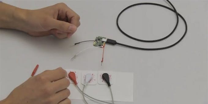
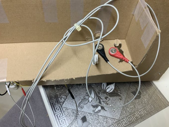
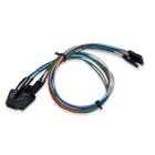
The next step is to solder the ECG leads onto the female jacks of the ECG cables.
Then, snap the wet electrodes or biomedical sensor pads onto the ECG cable pads.
If you need it to perform the long-term vital measurement, then fix the coin-cell holder provided with the MAXREFDES100#, it is a CR2032 coin-cell model. (preferably a rechargeable one, but even a conventional coin cell also works).
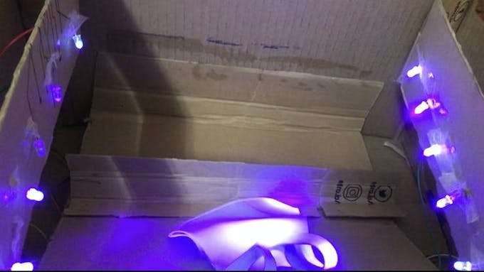
Regarding the mask sanitizer, you can also place a cardboard sheet across the entire area of the interior, so that you can cover up the electronics and further thermally shield them from the hot environment (cold environments are better as they reduce the resistance of the circuit to electronic flow), as well as provide a platform for the masks to be placed on. By the way, do not remove a mask once placed in unless it has been half an hour long or you believe it's enough sanitization from the UV-wavelength ionizing radiation.
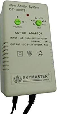
Using the Skymaster power supply, you can adjust the potentiometer to 12VDC and since it has many barrel jacks, cut off the smallest diameter barrel jack and solder the wires onto the breadboard rail that supplies the motor-transistor circuit with power and ground, the biggest barrel jack should be plugged into the Arduino Mega, and the polarity potentiometer should be set to +.
Features: Detection AND protection incorporated in project to be nominated for UNDP prize nomination
Detect: MAXREFDES100 uses advanced algorithms and medical-grade sensors, thus making it extremely reliable to detect and pre-emptively provide detailed readings to tremendously aid any assisting medical staff (even nurses) to help detect asymptomatic people as the blood oxygen percentage detected by the medical sensor board will drop due to increased viral RNA and increased cytokine molecules due to cell invasion will be circulating the blood as well, thus reducing the amount of oxygen detected by the optical sensor and acting as a makeshift blood test (it is a very good substitute for the RT-PCR test as can be used multiple times to test patients, and doesn't produce any contaminants or byproducts).
Protect: A hospital-grade mask sanitizer relying on cheap yet powerful Innotek UV-C LEDs and relies on 5VDC is very power-efficient and the low-power Arduino microcontroller coupled with an automatic hand sanitizer dispenser means that people can simply hold out their hand to collect soap and disinfectant, thus greatly reducing viral spreading by eliminating the need to visit other stations so spreading around potentially infectious microbes and viruses.
Additional benefits:
Relatively low cost: Normally such specialized stations can cost well over $500 for the same structure; however, the portable clinic offers the same features with enhanced structural integrity, since cardboard melts only at about 200 degrees Celsius and can provide thermal shielding from hot environments, at a greatly reduced price tag of about $200-300 for the whole thing, including the cardboard box.
Durability: Cardboard is cheap to buy, widely available in low-cost countries, and has excellent structural integrity. The wood fibers making up cardboard interior are strong and resilient. Cardboard is puncture resistant and does not tear easily. The arched design of the interior fluting lends durability to the cardboard as well.
Cardboard melts at 200 degrees Celsius so protects the interior of the portable clinic in very hot countries (not exceeding 120 degrees Celsius is recommended) and the hottest temperature recorded in the world's history (excluding the Large Hadron Collider) occurred at 56.7 degrees Celsius (134.1 °F) so all the components would be perfectly operational and shielded at that temperature.
Cardboard's wooden fibers shield the interior from any type of electromagnetic radiation in the EM spectrum up till UV-C radiation (so can be placed in polluted areas).
Still unsure. Then here are some reasons to use it in preference to other equipment sterilization machines:
Multi-purpose invention (one solution to many problems): As mentioned above, the portable clinic can diagnose symptomatic and asymptomatic patients of CoVID-19 and other underlying conditions with minimal help from a nurse or doctor, as well as help protect and slow down the spread of the disease by employing automatic disinfectant dispenser and a medical-grade mask sanitizer at a substantially low cost for communities, thus making it the ideal solution to drastically flatten the disease-time curve gradient(flatten the curve).
Highly and easily customizable: Parts can be added or removed and the Arduino MCU can be coded to allow you to run different, custom programs.
Energy-efficient and low-power consumption: The whole portable clinic (mask sanitizer, hand sanitizer, and MAXREFDES100) uses a mere 15V or 10V if using a power bank (3V coin cell+ 12V DC adapter) which means that at-risk communities will be easily able to power them without fearing for electricity overconsumption.
Interior is automatically oxygen-desiccating: Cardboard has excellent oxygen absorption and deprivation properties, meaning that any aerobically respiring microbes will die due to lack of sufficient oxygen if the UV-C light doesn't kill them, which is highly improbable.
Highly portable: This whole creation can be carried around very easily, like a U-Haul box so it will feel lighter than other equipment and can be carried around quickly to other hospital wards.
Biodegradable and recyclable: Cardboard is basically a formation of pulped up wood and paper so it is made of organic material and can be thrown away (no staples) in a field where decomposers (like fungi and bacteria) decompose it into the soil, which helps other plants to grow. #TeamTreesHack. and the components are all open-source so can be taken out of the machine when it has reached its end of service date, about 10 years in normal environments and 7-8 years in hot or cold environments, the Arduino can drive other projects and the peripherals as well can be repurposed, so all the machine's components end up helping the planet and people anywhere they will be.
Shock absorption: Cardboard's random interior fluting and the meshwork of cellulose spokes mean that it can be hit lightly and the interior components won't be damaged. You might have to change the position of the LDR by bending it so that the entire surface area of the LDR is covered by the laser.
This is my first project and I hope that it is good enough to win first place at the CoVID-19 Detect and Protect competition. I spent about 4 months working on this project just to provide you all with the same details that you all are going to build it using so that you don't go through the same brain-killing trouble that I faced. Please leave a like or comment below if you find it interesting and I will reply to it as soon as possible.
Everyone, the project is finally done. So, congratulations, you have the potential to pre-emptively diagnose CoVID-19 (provided a doctor or nurse is on call at the station) and call an ambulance and medical support in case someone has tested positive for CoVID-19 or any other underlying medical condition. I pray to God that it will not happen to any of you, as y'all are my community :). Stay safe. And also a big thank you to all the big technology and software makers who helped bring this truly ultimate solution to life.
 |
| × | 1 | |||
| × | 10 | ||||
 |
| × | 1 | |||
 |
| × | 1 | |||
 |
| × | 1 | |||
 |
| × | 1 | |||
| × | 1 | ||||
 |
| × | 1 | |||
 |
| × | 1 | |||
 |
| × | 2 | |||
 |
| × | 1 | |||
 |
| × | 1 | |||
 |
| × | 1 | |||
| × | 1 |
 |
| |||
 |
| |||
 |
| |||
| ||||
 |
| |||
 |
| |||
| ||||
|

.Coming from India, I realized that the SARS-CoV-2 virus could've been scanned, detected, and treated easily before becoming a full-blown pandemic. My idea is versatile, easy-to-assemble, and does much more than clean masks. It also sanitizes your hands with an automatic sanitization machine that relies on the power of Arduino and ARM platforms. It may be a bit challenging to make, but each one can detect and diagnose body vitals, thus offsetting the cost of making and deploying them. It uses the coding of C++ (Arduino IDE) to make the sanitation suite come to life. This project uses an Arduino Or Genuino Mega 2560.
Bill of materials
About USD $300 (AED 850.
Orientation video
https://youtu.be/Xmy4RtmoXII
Resources needed on the ground
Assuming that the project is placed in a populated and high risk community, the resources needed are-
Electricity output of 15VDC or 12VDC if running on a power supply, else just buy a power bank with 2 5V usb outputs and plug those into the Arduino USB and the hub USB.
Liquid disinfectant (Dettol or watered down soap solution) for the water atomiser and the hand sanitiser
Internal medicine doctor or cardiologist or even a nurse (to monitor and diagnose MAXREFDES100's readings)
Android phone (for Maxim Apk app) OR PC (Windows only) and the PC is recommended for detailed diagnosis using oximetry as the Android app doesn’t display SpO2 levels.
Structural Setup
Structural SetupCut 2x 10 cm by 25 cm cardboard sheets and line 2 strips of copper tape parallel to each other: one strip for the positive terminal (+) and one for ground (GND) And then solder 5 UV LEDs for each copper-cardboard fixture shown below.
Then, cut a rectangular hole- wide enough for the 16 x 2 I2C LCD to fit into.
ArduinoHardwareHookup
These connections only work if you’ve already soldered the UV-C bulbs on the copper-cardboard fixture mentioned somewhere above.
The connections are as follows:
I2C 16X2 LCD
I2C 16X2 LCDSCL- Pin 21
SDA- Pin 20
VCC- 5V (on the power section)
GND- GND (on the power section)
Copper-cardboard fixtures
Copper-cardboard fixturesGround wires to both the grounds at the end of the digital pin column
Jumper wire from pin 50 and 52 to the bases of both BC557 PNP transistors
Positive pin of copper-cardboard fixtures to the collectors of both BC557s
GND pins of fixtures to GND pin of breadboard rail (which also has a GND pin connected to the Mega)
Both emitter pins to 5V pin on the Mega 2560
Water Atomiser
VCC to 5V pin (which can be used to supply shields with 3.3V or 5V)
GND pin to the same ground rail as the LED strips.
EN pin to digital pin 40
Important: Only tape one of the copper-cardboard bulb fixtures for now. We need to tape the other one later after we have added the cardboard supports (strips which ensure structural integrity is maximum even if a heavy mask is dropped on the base).
Laserdiode
VCC (Red wire) --> 5V
GND (Blue wire) --> GND
3-pin light sensor
3-pin light sensorVCC --> 3.3V
GND --> GND
OUT (Signal) --> D48
Adjust the frequency (blue potentiometer) of the light sensor using a screwdriver until it turns off exactly when the laser is covered, and on when it is exposed to the laser.
ArduinoCodeSetup
#include <Wire.h>
#include <LiquidCrystal_I2C.h>

LiquidCrystal_I2C lcd(0x27,16,2);

void setup()
{
 pinMode(48,INPUT); //D48 is the digital light sensor
lcd.init();
lcd.noCursor();
lcd.backlight();
pinMode(50, OUTPUT);
pinMode(52,OUTPUT);
pinMode(40, OUTPUT);
lcd.backlight();
lcd.display();
lcd.clear();

}


void loop()
{

 if (digitalRead(48)) {
 delay(1000);
 lcd.clear();
 lcd.print(String("Lower the lid"));
 delay(500);
 lcd.clear();
 lcd.print(String("Wait 30 mins"));
 digitalWrite(50,LOW);
 digitalWrite(52,LOW);
 digitalWrite(40,HIGH); //D40 is the water atomiser
 delay(1800000);
 digitalWrite(50,HIGH);
 digitalWrite(52,HIGH);
 digitalWrite(40,LOW);
 lcd.clear();
 lcd.print(String("Remove the mask!"));

 } else {
 digitalWrite(50,LOW);
 digitalWrite(40,LOW);
 lcd.setCursor(0, 0);
 lcd.print(String("Please place"));
 lcd.setCursor(0, 1);
 lcd.print(String("a mask in!"));

 }

}
#include <Wire.h>
#include <LiquidCrystal_I2C.h>

LiquidCrystal_I2C lcd(0x27,16,2);

void setup()
{
  pinMode(48,INPUT); //D48 is the digital light sensor
lcd.init();
lcd.noCursor();
lcd.backlight();
pinMode(50, OUTPUT);
pinMode(52,OUTPUT);
pinMode(40, OUTPUT);
lcd.backlight();
lcd.display();
lcd.clear();

}


void loop()
{

    if (digitalRead(48)) {
      delay(1000);
      lcd.clear();
      lcd.print(String("Lower the lid"));
      delay(500);
      lcd.clear();
      lcd.print(String("Wait 30 mins"));
      digitalWrite(50,LOW);
      digitalWrite(52,LOW);
      digitalWrite(40,HIGH); //D40 is the water atomiser
      delay(1800000);
      digitalWrite(50,HIGH);
      digitalWrite(52,HIGH);
      digitalWrite(40,LOW);
      lcd.clear();
      lcd.print(String("Remove the mask!"));

    } else {
      digitalWrite(50,LOW);
      digitalWrite(40,LOW);
      lcd.setCursor(0, 0);
      lcd.print(String("Please place"));
      lcd.setCursor(0, 1);
      lcd.print(String("a mask in!"));

    }

}
Autohandsanitizer
This addition to the project is crucial as it provides people one stop to clean masks and sanitise their hands. This sanitiser relies on an IR sensor (ultrasonic sensor requires much more code which is time consuming) and a 5V 500 mA peristaltic pump from Adafruit and works without a microcontroller which saves time and a lot of money. It relies on a TIP42C PNP transistor, to turn on the pump when the IR sensor detects an object nearby.
Transistor Base to IR sensor OUT
Collector to positive of motor
Emitter to positive of breadboard rail
IR sensor VCC to breadboard positive rail
IR sensor GND to breadboard negative (ground) rail
Add an image
Delete this image
Disclaimer: I would strongly recommend that you rely on the wiring setup instruction in words, not the picture above. Fritzing is old and depreciated but I had no choice but to use it. The arrangement for different kinds of PNP transistors vary depending on the PNP model type. Here are the universal connections for PNP transistors in my project. I apologize if this causes any kind of trouble.
MAXREFDES100(MAX32620HSP) Software Setup
Note (MAXREFDES100 Setup)
Note (MAXREFDES100 Setup)Now, I know what you all are thinking: It's pretty expensive to be classified as a low-cost solution. However, the distribution of the machines should be trilaterally placed, meaning 3 of them should be placed at points in different villages, towns, etc. such that they are easily accessible by people in ambulances. Let's take Africa as an example: There are 22 underdeveloped nations (underdeveloped meaning no monitoring and diagnosis tools present in the entire area of the nation) in Africa, and we will take the biggest landmass and the biggest population. So Congo is the largest underdeveloped nation at a landmass of about 2, 344, 858 sq km (905, 355 sq mi), and Nigeria has the most population of about 200 million individuals as of December 2019. So the machines need to be placed at an average distance of 3 km away from each other. This is because African people walk on average about 4 km a day to collect water from wells, so they can walk that distance or be carried in an ambulance to the medical camp. These machines can also be rented by different ambulances with different time slots registered, with an extra 3 to 4 in place for emergencies. This device also contains defibrillation protection and can measure SpO2 concentration (blood oxygen level), BPM, body temperature and ECG readings, as well as with different LEDs, and environmental pressure to see if strain occurs because of heat, which an amateur cardiologist can read to determine whether the person has an underlying condition, and help to pre-emptively send the person for a CoVID-19 test (RT-PCR or UAE's new laser test) or to send them to a hospital to be treated for any signs of flu, or any disease that is directly linked to respiratory and cardiological damage. Thus, the cost of one machine offsets about 10 peoples worth of CoVID-19 critical stage treatment. In other words, helping to diagnose CoVID-19 in its primary stage or any other underlying condition that non-CoVID-19 sufferers are usually neglected or delayed treatment for is heavily relied on by using my machine
Now onto the actual setup:
I will only discuss how to set the HSP board up on the GUI and Android app. For more detail on how to set it up, please refer to the MAXREFDES100's product page. This is preferred or if you aren’t a visual learner: click on this video for setup instructions.
Hardware and Software Setup
Insert the USB-C port of the HDK adapter into the HSP's port, and insert a micro-USB cable into the HDK port of the adapter and insert the other end into your computer.
Add an image
Delete this image
Press the only button on the sensor board for half a second and wait till the red LED lights up.
Then, on your PC, you should see a notification pop up, saying that COM10's setup is complete. (This allows us to upload custom firmware for the board if you want to later.)
Go to Device Manager and click on COM Ports (LPT) and check if the COM port exists.
Then, unplug the HDK adapter from your PC and simply plug a USB-C cable from the sensor board to the computer to set it up with the GUI
Then wait for a few minutes until a notification pops up saying "USB Serial Device (COM11) is set up)
Then, click this link to download the GUI or check it out on the product page.
After downloading the GUI for the first time, a window displaying UART configuration pops up beginning with a baud rate of 9600. Simply click Scan Ports to find COM11 (or whichever COM port the USB serial device is on) and then click Connect.
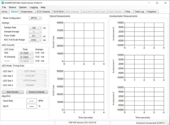
Then this page should pop up
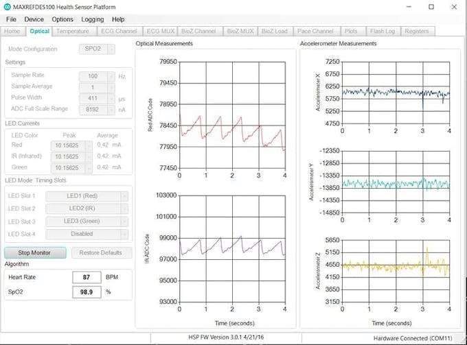
Click on the Optical tab and place your thumb or finger on the slightly large glass window with a red LED flashing on it.
Then click Start Monitor
Some readings should pop up 👆
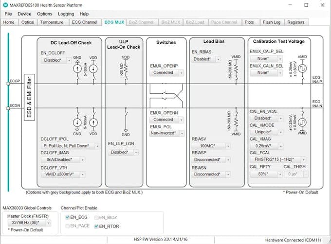
Click the ECG MUX and select ECG OPENP and OPEN-N and select Connected.
Then enable EN_ECG and EN_RTOR (ECG and R-R if MAX30003 register names are disabled)
Then click on the Plots tab and select start monitor.
An ECG pulse should be showing up, provided the cables are soldered onto the board or pushed in using male header pins of jumper wires as well.
Click Temperature and blow on the sensor board. The temp. sensor readings should then rise.
That's all for the PC app.
Now let's move over to the Android app.
https://www.maximintegrated.com/en/design/software-description.html/swpart=SFW0007670A
Then click the file name and download the.zip folder
Click on the.apk file and copy it to your Google Drive (BlueStacks in the above picture).
Then, jump on to your Android phone and open the.apk file on Google Drive.
Download the.apk file and a page should pop up which scans for BLE ports
MAXREFDES100 should pop up under the list of available devices.
Then, tap the MAXREFDES100
Then, another page should pop up indicating the values of different sensors.
However, the optical sensor measurements and SpO2 levels are not indicated on this. Only, Windows PCs can show the temperature, ECG, and SpO2 levels necessary for patient monitoring. In this case, each location where the machine is placed should have a nearby PC with the GUI installed or simply for ECG measurement, a phone can be used to measure the effects of the environmental conditions on the person's state of health.
Structural Setup
Place the MAXREFDES100 sensor board into a nice cardboard enclosure, like a tiny cardboard box that exposes the top part of the board which is the part containing the blood oxygen concentration optical sensor window.
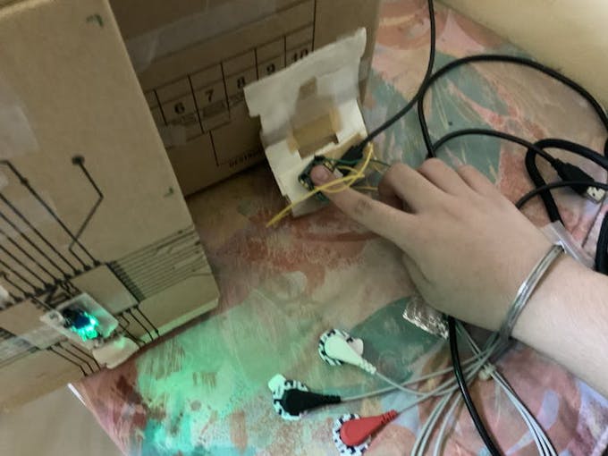
The next step is to solder the ECG leads onto the female jacks of the ECG cables.
Then, snap the wet electrodes or biomedical sensor pads onto the ECG cable pads.
If you need it to perform the long-term vital measurement, then fix the coin-cell holder provided with the MAXREFDES100#, it is a CR2032 coin-cell model. (preferably a rechargeable one, but even a conventional coin cell also works).
Regarding the mask sanitizer, you can also place a cardboard sheet across the entire area of the interior, so that you can cover up the electronics and further thermally shield them from the hot environment (cold environments are better as they reduce the resistance of the circuit to electronic flow), as well as provide a platform for the masks to be placed on. By the way, do not remove a mask once placed in unless it has been half an hour long or you believe it's enough sanitization from the UV-wavelength ionizing radiation.
Using the Skymaster power supply, you can adjust the potentiometer to 12VDC and since it has many barrel jacks, cut off the smallest diameter barrel jack and solder the wires onto the breadboard rail that supplies the motor-transistor circuit with power and ground, the biggest barrel jack should be plugged into the Arduino Mega, and the polarity potentiometer should be set to +.
Features: Detection AND protection incorporated in project to be nominated for UNDP prize nomination
Detect: MAXREFDES100 uses advanced algorithms and medical-grade sensors, thus making it extremely reliable to detect and pre-emptively provide detailed readings to tremendously aid any assisting medical staff (even nurses) to help detect asymptomatic people as the blood oxygen percentage detected by the medical sensor board will drop due to increased viral RNA and increased cytokine molecules due to cell invasion will be circulating the blood as well, thus reducing the amount of oxygen detected by the optical sensor and acting as a makeshift blood test (it is a very good substitute for the RT-PCR test as can be used multiple times to test patients, and doesn't produce any contaminants or byproducts).
Protect: A hospital-grade mask sanitizer relying on cheap yet powerful Innotek UV-C LEDs and relies on 5VDC is very power-efficient and the low-power Arduino microcontroller coupled with an automatic hand sanitizer dispenser means that people can simply hold out their hand to collect soap and disinfectant, thus greatly reducing viral spreading by eliminating the need to visit other stations so spreading around potentially infectious microbes and viruses.
Additional benefits:
Relatively low cost: Normally such specialized stations can cost well over $500 for the same structure; however, the portable clinic offers the same features with enhanced structural integrity, since cardboard melts only at about 200 degrees Celsius and can provide thermal shielding from hot environments, at a greatly reduced price tag of about $200-300 for the whole thing, including the cardboard box.
Durability: Cardboard is cheap to buy, widely available in low-cost countries, and has excellent structural integrity. The wood fibers making up cardboard interior are strong and resilient. Cardboard is puncture resistant and does not tear easily. The arched design of the interior fluting lends durability to the cardboard as well.
Cardboard melts at 200 degrees Celsius so protects the interior of the portable clinic in very hot countries (not exceeding 120 degrees Celsius is recommended) and the hottest temperature recorded in the world's history (excluding the Large Hadron Collider) occurred at 56.7 degrees Celsius (134.1 °F) so all the components would be perfectly operational and shielded at that temperature.
Cardboard's wooden fibers shield the interior from any type of electromagnetic radiation in the EM spectrum up till UV-C radiation (so can be placed in polluted areas).
Still unsure. Then here are some reasons to use it in preference to other equipment sterilization machines:
Multi-purpose invention (one solution to many problems): As mentioned above, the portable clinic can diagnose symptomatic and asymptomatic patients of CoVID-19 and other underlying conditions with minimal help from a nurse or doctor, as well as help protect and slow down the spread of the disease by employing automatic disinfectant dispenser and a medical-grade mask sanitizer at a substantially low cost for communities, thus making it the ideal solution to drastically flatten the disease-time curve gradient(flatten the curve).
Highly and easily customizable: Parts can be added or removed and the Arduino MCU can be coded to allow you to run different, custom programs.
Energy-efficient and low-power consumption: The whole portable clinic (mask sanitizer, hand sanitizer, and MAXREFDES100) uses a mere 15V or 10V if using a power bank (3V coin cell+ 12V DC adapter) which means that at-risk communities will be easily able to power them without fearing for electricity overconsumption.
Interior is automatically oxygen-desiccating: Cardboard has excellent oxygen absorption and deprivation properties, meaning that any aerobically respiring microbes will die due to lack of sufficient oxygen if the UV-C light doesn't kill them, which is highly improbable.
Highly portable: This whole creation can be carried around very easily, like a U-Haul box so it will feel lighter than other equipment and can be carried around quickly to other hospital wards.
Biodegradable and recyclable: Cardboard is basically a formation of pulped up wood and paper so it is made of organic material and can be thrown away (no staples) in a field where decomposers (like fungi and bacteria) decompose it into the soil, which helps other plants to grow. #TeamTreesHack. and the components are all open-source so can be taken out of the machine when it has reached its end of service date, about 10 years in normal environments and 7-8 years in hot or cold environments, the Arduino can drive other projects and the peripherals as well can be repurposed, so all the machine's components end up helping the planet and people anywhere they will be.
Shock absorption: Cardboard's random interior fluting and the meshwork of cellulose spokes mean that it can be hit lightly and the interior components won't be damaged. You might have to change the position of the LDR by bending it so that the entire surface area of the LDR is covered by the laser.
This is my first project and I hope that it is good enough to win first place at the CoVID-19 Detect and Protect competition. I spent about 4 months working on this project just to provide you all with the same details that you all are going to build it using so that you don't go through the same brain-killing trouble that I faced. Please leave a like or comment below if you find it interesting and I will reply to it as soon as possible.
Everyone, the project is finally done. So, congratulations, you have the potential to pre-emptively diagnose CoVID-19 (provided a doctor or nurse is on call at the station) and call an ambulance and medical support in case someone has tested positive for CoVID-19 or any other underlying medical condition. I pray to God that it will not happen to any of you, as y'all are my community :). Stay safe. And also a big thank you to all the big technology and software makers who helped bring this truly ultimate solution to life.
Replace regular lcd with an i2c lcd.
For Motor: TIP42C PNP: Base --> Digital IR sensor out, Collector --> Positive of peristaltic pump, Emitter --> 12V out from USB cable
