Trybotics Logo

PWM Demonstration Board (Using Arduino) © GPL3+

DESCRIPTION

Overview

The main objective of this project is to help people understand the concepts behind PWM. What is it and how it works.

Some students have problems understanding how PWM works, so I decided to build an Arduino shield, that using the Arduino PWM outputs and some easy code, can demonstrate with the help of an osciloscope, how PWM works.

The shield is not mandatory. The circuit can be easily put together in a Breadboard. However if you want a more permanent system, I recomend building the shield.

This circuit can also do other things like demonstrating the charge and discharge of a capacitor, with the help of an osciloscope.

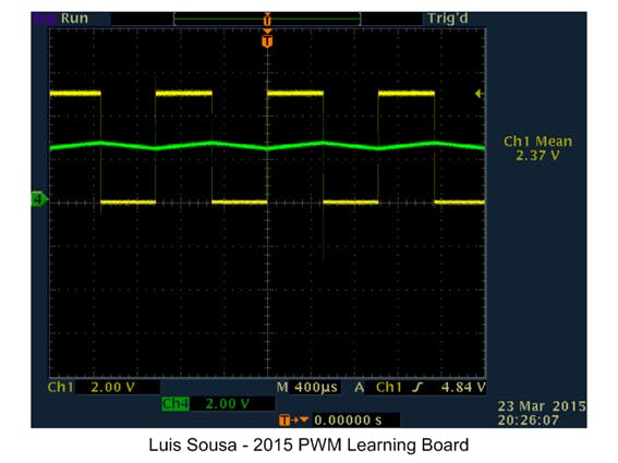
Or demonstrating how duty cycle affects the mean value:

This project also gives the oportunity to the student to familiarize with the Arduino platform capabilities. We will use Analog input, Digital outputs and PWM outputs.

Operating Instructions:

This project has 2 working modes:

  • PWM mode (Selectable via Pin D4 = logic 1)

In this mode, we use pins 10 and 11 to generate two complimentary PWM signals that control 2 LEDs (red and green). The duty cycle is dependent of the analog value present at analog Input A0. This analog value is commanded via a potentiometer. Changing the duty cycle, changes the mean value and the luminosity of the LEDs. (One LED increases luminosity, the other decreases).

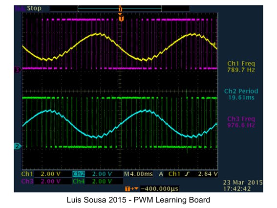
Pins 5 and 6 have a complimentary PWM signal with a duty cycle that varies continuously at a sinusoidal rhythm. Applying a RC filter we can observe a sinusoidal signal.

  • Pulse generation mode (Selectable via Pin D4 = logic 0)

With this operating mode, we have on pins D0 and D1 pulses with 10% and 90% duty cycle. On pin 13 we have rectangular wave (500Hz) with a 50% duty cycle

On pins 5 and 6 we have now complimentary square waves that are applied to RC network. We can see at the capacitor terminals the charge discharge curves.

Description:

Description:

Overview

The main objective of this project is to help people understand the concepts behind PWM. What is it and how it works.

Some students have problems understanding how PWM works, so I decided to build an Arduino shield, that using the Arduino PWM outputs and some easy code, can demonstrate with the help of an osciloscope, how PWM works.

The shield is not mandatory. The circuit can be easily put together in a Breadboard. However if you want a more permanent system, I recomend building the shield.

This circuit can also do other things like demonstrating the charge and discharge of a capacitor, with the help of an osciloscope.

Or demonstrating how duty cycle affects the mean value:

This project also gives the oportunity to the student to familiarize with the Arduino platform capabilities. We will use Analog input, Digital outputs and PWM outputs.

Operating Instructions:

This project has 2 working modes:

  • PWM mode (Selectable via Pin D4 = logic 1)

In this mode, we use pins 10 and 11 to generate two complimentary PWM signals that control 2 LEDs (red and green). The duty cycle is dependent of the analog value present at analog Input A0. This analog value is commanded via a potentiometer. Changing the duty cycle, changes the mean value and the luminosity of the LEDs. (One LED increases luminosity, the other decreases).

Pins 5 and 6 have a complimentary PWM signal with a duty cycle that varies continuously at a sinusoidal rhythm. Applying a RC filter we can observe a sinusoidal signal.

  • Pulse generation mode (Selectable via Pin D4 = logic 0)

With this operating mode, we have on pins D0 and D1 pulses with 10% and 90% duty cycle. On pin 13 we have rectangular wave (500Hz) with a 50% duty cycle

On pins 5 and 6 we have now complimentary square waves that are applied to RC network. We can see at the capacitor terminals the charge discharge curves.

Description:

Arduino_PWM_Demo_Board_V13.inoArduino
This is the code i wrote
/* Arduino PWM Demo Board
 2015 Luis Sousa */

//Definio dos pinos
int pulse_1 = 0;    // pulse 10% on no pino x
int pulse_2 = 1;    // pulse 10% off no pino x
int pulse_3 = 2;    // inverter pulse 50% no pino x
int pulse_4 = 3;    // inverter pulse 50% no pino x
int pulse_5 = 5;    // 20ms 50 hz 50% no pino x
int pulse_6 = 6;    // 20ms 50 hz 50% invertida no pino x
int sin_1 = 5;      // saida sinusoidal 1 no pino x
int sin_2 = 6;      // saida sinusoidal 2 no pino x
int clk = 13;       // clock no pino x
int led_1 = 10;     // led 1 no pino x
int led_2 = 11;     // led 2 no pino x
int switchPin = 4;  // Comuta modo 1 ou modo 2 no pino x

// Inicializao de variaveis
int analog_1 = 0;  //Valores da sinusoide 1
int analog_2 = 0;  //Valores da sinusoide 2
float x = 0;
int us = 975;
int vin = 0;
int vout = 0;
boolean fixed_pulse = false; //permite variar a frequencia dos impulsos no modo 2

void setup()
{
  pinMode(pulse_1, OUTPUT);
  pinMode(pulse_2, OUTPUT);
  pinMode(pulse_3, OUTPUT);
  pinMode(pulse_4, OUTPUT);
  pinMode(pulse_5, OUTPUT);
  pinMode(pulse_6, OUTPUT);
  pinMode(sin_1, OUTPUT);
  pinMode(sin_2, OUTPUT);
  pinMode(led_1, OUTPUT);
  pinMode(led_2, OUTPUT);
  pinMode(clk, OUTPUT);        //clock & LED de monitorizaao
  pinMode(switchPin, INPUT);   //Comuta modo 1 ou modo 2
  pinMode(7, OUTPUT);          // seleccao de modo. Pino 7 liga switchPin
  digitalWrite(7, HIGH);     // seleccao de modo. Pino 7 LOW/HIGH
}

void loop()
{


  if (digitalRead(switchPin) == LOW) // Modo 2 - Gerador de impulsos
  {
    //T0
    digitalWrite(clk, !(digitalRead(clk)));
    digitalWrite(pulse_1, HIGH);
    digitalWrite(pulse_2, LOW);
    digitalWrite(pulse_5, !(digitalRead(pulse_5)));
    digitalWrite(pulse_6, !(digitalRead(pulse_5)));
    digitalWrite(pulse_3, digitalRead(pulse_5));
    digitalWrite(pulse_4, digitalRead(pulse_6));
    delayMicroseconds(us-55);
    //delay(1);

    //T1
    digitalWrite(clk, !(digitalRead(clk)));
    digitalWrite(pulse_1, LOW);
    digitalWrite(pulse_2, HIGH);
    delayMicroseconds(us);
    //    delay(1);

    //T2
    digitalWrite(clk, !(digitalRead(clk)));
    delayMicroseconds(us);
    //    delay(1);

    //T3
    digitalWrite(clk, !(digitalRead(clk)));
    delayMicroseconds(us);
    //    delay(1);

    //T4
    digitalWrite(clk, !(digitalRead(clk)));
    delayMicroseconds(us);
    //    delay(1);

    //T5
    digitalWrite(clk, !(digitalRead(clk)));
    delayMicroseconds(us);
    //    delay(1);

    //T6
    digitalWrite(clk, !(digitalRead(clk)));
    vin=analogRead(0);
    delayMicroseconds(us-100);
    //    delay(1);

    //T7
    digitalWrite(clk, !(digitalRead(clk)));
    if (!fixed_pulse) us = 500 + vin;
    delayMicroseconds(us);
    //    delay(1);

    //T8
    digitalWrite(clk, !(digitalRead(clk)));
    delayMicroseconds(us);
    //    delay(1);

    //T9
    digitalWrite(clk, !(digitalRead(clk)));
    delayMicroseconds(us);
    //    delay(1);

  }
  else // Modo 1 Gerador de sinusoide PWM + Controlador PWM
  {
    x = x + 15;
    if (x > 628) x = 0;
    vin = analogRead(0);
    vout = int(vin / 4); // 1023/4 = 255, valor maximo que se pode escrever num porto PWM (8 bit)

    analog_1 = int(128 + (vout / 2) * (sin(x / 100)));
    analog_2 = int(128 + (vout / 2) * (sin(3.14 + x / 100)));
    analogWrite(sin_1, analog_1);
    analogWrite(sin_2, analog_2);
    analogWrite(led_1, vout); // Saida PWM 1
    analogWrite(led_2, 255 - vout); //Saida PWM 2 simetrica da 1
    //digitalWrite(clk, !digitalRead(clk));
  }

}

Description:

PWM Learning Board Shield Schematic Diagram
Eagle File
shield_6_BLoLreKcID.sch
PWM Learning Board Shield Board Layout
Eagle File
shield_6_ZzRFKgYWPJ.brd
PWM Learning Board Shield Schematic Diagram
JPG Image of PWM Learning Board Circuit. If you dont have Eagle software installed on you computer, you can view the Circuit Image
Pwm board circuit diagram gihp5gn861
PWM Learning Board Shield PCB Diagram
JPG image of PCB. If you dont have Eagle software installed on you computer, you can view the PCB Image
Pwm board pcb diagram hmxtsecb78


YOU MIGHT ALSO LIKE