Smart Garage Model by Blynk and XOD
DESCRIPTION
Video
Intro
Greetings, people!
Smart house concepts are no longer a novelty, and smart devices take a significant part of our lives. It is mainly made possible by the Internet of Things (IoT) networks which connect various electronic devices. With the IoT, you can automate your house with the smart temperature and humidity controllers, or remotely control lights, kettle, or even vacuum cleaner. Based on the trend of popularity, each house will become smart soon.
Of course, a smart home can be bought. However, I think it is better to make it smart by yourself, isn’t it? Nowadays, there are many different applications which allow anyone unfamiliar with electronics or programming to implement their ideas. In my opinion, it’s easier to understand the details of the topic while doing everything from scratch. Besides, the result will be much more valuable.
It's time for me to figure out how it works. For this, I decided to create an automated garage and describe the process in this article. In a fact, I have no spare garage, so I decided to build a smart garage model from the toy building.
Those who are unfamiliar with programming can find this article very useful because I’ll tell how to make it work without writing a single line of code. Let me share the experience.
Workpiece


It’s a two-story building made of wood. The garage occupies the ground floor, and there is a workshop on the second floor. In front of the building, there are three garage gates. On the opposite side, the building has a lift to the workshop and two additional entrances. The blue door leads to the workshop from the roof of the garage. The workshop roof can be opened to access inside. All gates in the garage open up.
This toy has a lot of moving parts, and it is large and inexpensive. In my opinion, it is ideal to practice the process of a smart house model creation.
Idea
First of all, the garage needs to get a “brain” to be smart. I took Arduino because it is easy to start with.
With Arduino controller, I’m going to operate various electronic devices and components at the garage as well as process data from sensors.
If my garage will become smart, how do I communicate with it?There are many technologies that enable IoT. A communication can be wired, for example via Ethernet. Or it can be wireless. Wireless networks use different protocols with the different ranges of action. The examples are Wi-Fi,RFID (Radio-frequency identification), NFC (Near-field communication), Bluetooth and so on. I think that garages, unlike smart homes, don't usually have high-quality wireless Internet.
I chose Bluetooth. Using this protocol I can control the garage with my smartphone whenever I need it. It is quite practical cause the phone is almost always at hand.
For the garage management, I’ll use a mobile application at my smartphone.
Hardware
I purchased all the necessary electronic components in one place. Surely you can find analogs at your local stores.
I chose the Arduino Mega 2560 microcontroller. This board has lots of digital and analog ports, supports many interfaces and it is sufficiently efficient. If you are planning to repeat the experiment, you can use any other microcontroller and board you like.

To connect my smartphone to Arduino via Bluetooth I’m going to use BLE (Bluetooth Low Energy) wireless technology. iOS, Android, Windows Phone Mobile operating systems natively support Bluetooth Low Energy so the connection shouldn’t be a problem no matter what smartphone model you have. For Arduino, I use this BLE HM-10 module based on a CC4051 microchip.

For the connecting convenience, I’ll use some Arduino expansion boards and pads for modules.

Since I don’t use a real building, I don’t need real electronic devices, or light bulbs, or other 220V powered equipment. Let it be the next step after my automatization model. Therefore, I can use hobby electronic components: LEDs, servos, sensors, etc.

Installation
Let's feature the garage.
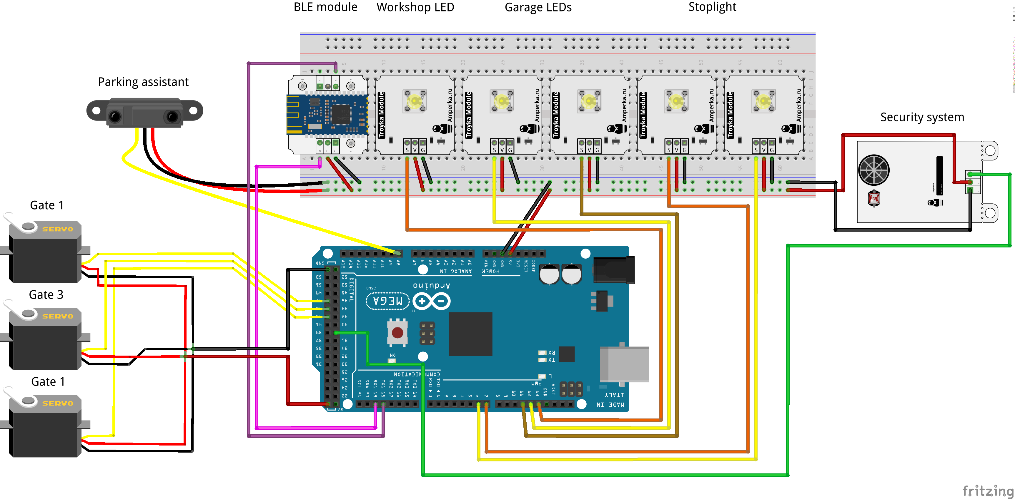
At first, I choose a place for the Arduino Mega board. Let it be on the ground floor inside of the garage. There is some open space around, so I can access the board ports to connect modules and components.

The BLE module takes its place on the wall backside of the garage, so I can monitor the LEDs on the board indicating the Bluetooth connection status.

Let’s add some movement to the garage. The obvious solution is the front gates opening automatization. I attached these gates to three FS90 servos using the PVC blocks. Then I mount servo arms to the gate frames., I will open and close the gates by setting the servo values.

As any real room, the garage and the workshop should have a light. For this, I place two bright LEDs on the opposite walls on the ground floor and one LED on the second floor.


Time to add some smart sensors. I decided to make a parking assistant for the central garage box. For this, I use a GP2Y0A41 range meter by SHARP with the measuring range from 4 to 30 cm. I fix it by studs at the end of the garage box a short distance from the floor.

Suppose that lots of valuable things are stored at the workshop. For their safety, a security system should be installed at the workshop. I use the infrared motion sensor that reacts on the movement of a warm object, such as a human body. This kind of alarm is almost like the real thing. I mount this sensor on the workshop window.

What else to add? I decided to add the stoplight in front of one garage box. Of course, ordinary people don’t mount them on their building. Suppose this garage box is a car wash or a tire service, and the stoplight notifies customers. The stoplight is made of ordinary green and red LED.

I reckon these functions are enough to begin to work with. When all modules and components are fixed to the toy garage, I can define Arduino ports and connect them using wires to the board. Before programming the controller, I create a remote control.
Blynk
As I wrote above, I decided to control the garage remotely using a mobile application. But, how it can be done?
If you are familiar with programming and creating mobile applications, it is a piece of cake. However, this task is almost impossible for regular smartphone users. For those who still want to create their applications, there are lots of ready-made solutions. Spending some time choosing a mobile software I found Blynk.
Blynk software specially designed for IoT projects and it is compatible with most popular microcomputers and microcontrollers, including Arduino. What is even better is that it doesn’t require programming skills. So I will also take advantage of this software and create my application.
Next, I describe the process of making my remote control application. The detailed information can be found in the official Blynk documentation.
Making Application
At first, download and install the Blynk application on your Android or iOS smartphone.

Create a new Blynk account and log in.

Create a new Blynk project after login. Input the name of your project. Chose the device and connection type and press the “Create Project” button. I named my application “smart-garage”. According to the hardware I use, the device and connection types for my project are Arduino Mega and BLE respectively.

Check your Email address after creating the project. You’ll be sent a unique 32 digit token for your application. This token is used to pair your application with the hardware. Just write it down somewhere not to forget.

When you open the created project, you can see an empty workspace. Various elements called “Widgets” are placed on this workspace. Look at the full list of widgets at the Widget Box by swiping the screen to the left.

Please note, placing the widget on the workspace you spend “Blynk energy”. This resource isn’t free, so it is better to think over what your application should look like before buying widgets.
Widgets have different functions and are divided into groups. A widget can serve as a controller and send data to your IoT device, for example, Button or Slider. Another widget receives data from the device and shows it on the smartphone screen, for example, Value Display or LED. Some widgets can notify a user using a variety of services Twitter, Email) or even be utilities (Bridge, BLE, Real-time clock).
When I came up with the app, I begin to add widgets. The first widget that I need is BLE. This widget is used to enable Bluetooth Low Energy support.

Next, I add widgets to control the lights in the garage and workshop. I want the workshop light to be controlled by the push of a button. So, I put a Button widget into the workspace.

Now I need to configure the Button settings. For each widget which sends or receives values, you should set up a PIN. Blynk can control Digital and Analog Pins on your hardware directly, but often it’s just not enough. In Blynk, there is a concept of a “virtual pin” to be used in complex projects or custom implementations. This is the pin type I use in my application for all widgets. You can choose the available virtual pin number in the widget options. Also, you can customize your widget, change its color, name, size, switch the operating mode or change range for input and output values.
I name my button workshop-light and choose V1 virtual pin. Also, I make it act as a switch and change its color. workshop-light button outputs either 0 or 1 depending on a state. These values are going to turn on and off the LED in my workshop.

The control for the workshop light is ready, and now it is time for the light in the garage. I addition to turning the garage light on and off, I want to control its brightness. The Slider widget helps me. This widget can output values in a set range, depending on a slider position. I put it into the workspace, name it garage-light, bind it to the V2 virtual pin and change other properties that I want. The Slider outputs values in the range from 0 to 255 by default.

Next, I add gate control. For three gates I need 3 more buttons. I name them gate 1, gate 2, and gate 3. Let the virtual pins for these widgets be V3, V4, and V5 correspondingly. Also, I change them into switches and name the on/off states of this buttons as closed and opened.

I need one more switch to control the stoplight. I attach the switch to the V6 virtual pin and name the on/off states Stop and Go.

By now, all placed widgets are used only to send values. For my security system and parking sensor, I need feedback from the smart garage.
I want the current distance to an obstacle to be displayed on my screen. For this, I’m going to use the Labeled Value widget. I add it to the Blynk workspace of my application and name it parking-assistant. As for the previous widgets, I set a virtual pin. For the parking-assistant it is V7. Also, I need to make some additional settings. At the Label you can set what part of value or text will be displayed continuously and what part will change. I want a Distance: prefix before the value, so I put the Distance: /pin/ value in the field. At the Refresh interval, you can set the time for a value to be updated. I set up this field to Push to update the distance value by a microcontroller signal instead of constantly asking it for a new value.

I want to set the proper distance to the obstacle for the oncoming car at the garage box. For example, if the distance is less than 5 cm, the transport must stop. To display whether the specified distance has been reached, I need an indication. For this, I add a LED widget. The widget will change the color depending on the current distance to the obstacle. I attach the LED widget to the V8 virtual pin.

Now I’m going to add a widget for my security system. To notice the application user I also use the Labeled Value widget. Let the static part of the text in this widget be Status: , and the dynamic part of the text be ALARM if a sensor has seen a warm object. If everything is quiet at the workshop and no alarm is needed, the status field will be empty. For the security system widget, I chose the V9 virtual pin. The Label value is Status: /pin/ and the Refresh interval value is Push.

The remote control application is done. Let’s put it aside for a while and program the microcontroller.
XOD
I didn’t write a single line of code to create the program for the controller. I used the XOD visual programming environment. Instead of writing code, here, special blocks called “Nodes” are used. More information can be found on the documentation page at the XOD web site.
To make Blynk compatible program, I still had to make the gabbapeople/blynk library to support blynk in XOD. But if you want to repeat the experiment you just need to add the library to your workspace and use the ready-made nodes. Also, you can find the prepared patch in the gabbapeople/blynk library.
Here are steps required to reproduce my program.
Making Program
Create a new project and name it. I named it the same as the smartphone application.
Add the init-ble-uart node from the gabbapeople/blynk library the onto the patch. This node is necessary for the HM-10 BLE module operation.

Fill in the AUTH value field. Do you remember the 32-digit token that came to your e-mail? The AUTH pin is the place for this token. Thus, XOD and Blynk can identify each other.
A pulse on the INIT pin initializes a BLE device. The RUN pin is used to synchronize the application with the microcontroller.
The init-ble-uart node outputs the BLNK custom type which is necessary for other Blynk nodes to exchange values with widgets.
Since the HM-10 BLE module communicates with the Arduino board via UART, the UART type value must be set to the similar input pin of the node.

Initialize the interface. Arduino Mega Board has 3 additional Hardware UART interfaces, so, it makes sense to use them. I connected the BLE module to the 18 and 19 Rx and Tx ports of the first hardware UART interface. Then, I put the uart-1 node from the xod/uart library and link it with the init-ble-uart node. You can use a hardware or software UART interface you want.
For the HM-10 BLE module, the BAUD rate is 9600. Link the DONE pin of your UART node with the INIT pin of the init-ble-uart node to initialize the BLE module when the UART interface is ready.
It is better to set the RUN pin value to Continuously in order not to accidentally disrupt the application synchronization.
For the BLNK pin, I decided to make a bus for the visual convenience of the subsequent nodes. It can be done by selecting the BLNK pin and pressing the B key on the keyboard.
Now, using the nodes, I’m going to describe each function of the smart-garage. The light control is the first function of my program. The light widgets in my smartphone app send values via Bluetooth, so the controller should read and process them.
To read data from the Blynk application use the read node from the gabbapeople/blynk library.

The BLNK pin of the read node expects the BLNK type value. Set VPIN to choose the virtual pin to read data from. This VPIN values refer to those virtual pins that are used for widgets in the application. Pulse on the READ pin triggers a new reading of data. The DATA pin outputs a String type value from the selected virtual pin.
Now, let’s create nodes to control the workshop light. For this, I put the read node onto the patch and link it with the init-ble-uart node using the existing BLNK bus. The workshop-light widget attached to the V1 virtual pin, so I put the 1 value to the VPIN. I set the READ pin value to Continuously.
I’ve got one LED at the workshop. Therefore, I put led node onto the patch and name it workshop-led. LED is connected to the 13 digital Arduino port, so I put the 13 value to the PORT pin of the led node.
The workshop-light widget outputs either 0 or 1 value, depending on the switch state. With this range of values, I can link the LUM pin of the led node with the DATA output of the read node directly. The only thing I have to do, it is to convert the value from the String to Number. For this, l use the parse-number node. This node can be found in the gabbapeople/uart-led-control library, so I should add it to my XOD workspace too.
Now, all I have to do is to link the read and led nodes through the parse-number. Here's a patch that I came up with.

Next, I continue with the garage light. The garage-light widget outputs values, so I need the read node again. The program for it is almost the same except for some details. The garage light is made by two LEDs instead of one, so I put an additional led node onto the patch. The garage-light slider widget at my remote control application tunes brightness and outputs a value in the range from 0 to 255. The led node, in its turn, inputs LUM values in a range from 0 to 1. To set up new ranges, I’ll use the map-clip node and put it between led and parse-number.
Garage LEDs are connected to the 11 and 12 Arduino pins. The VPIN value at the read node is 2 as it is relevant to the V2 virtual pin at the widget. Here is the second branch of the patch.

Next, let’s program servos on the gates. I’ve got three gates mechanized by three servos. Servos are connected to the 43, 45, and 47 digital Arduino Mega pins. I put three servo nodes from the xod/common-hardware library. They are controlled by three button widgets at the application, and I need to put three read nodes. For this widgets, the VPIN values at read nodes are 3, 4, 5.
A button widget outputs 0 or 1 value. The 0 to 1 range of a servo node means the 0 to 180 degree rotation. So, I use map-clip nodes and custom ranges to adjust the angles to make servos open and close gates properly.
Also, I want to update the servos if only a new value comes. For this, I add put three pulse-on-change nodes and link them with UPD pins. Look at new branches of the patch.

The last application widget that outputs values is stoplight. The program for it is pretty simple. Button push turns the green LED on, and the red LED off. Pressing the button widget again will change the state of the LEDs to the opposite. As previous, I need read and parse-number nodes, two led nodes for the red and green LED on my stoplight. I connect leds to the 6 and 7 Arduino pins and put relevant values to the PORT pin of the leds. The virtual pin for the stoplight widget is V6. To invert the signal from the button, I use the not node. Here is the stoplight branch of the program.

Now, I need to create a program for those widgets that input values from the controller and shows them at the smartphone screen. For this, the write node from the gabbapeople/blynk library is used.

A value at the VPIN targets an application widget to write DATA. A pulse on a PUSH pin triggers a new DATA send.
Let’s make a parking assistant program. In the xod/common-hardware library there is a gp2y0a41-range-meter node for the sensor I use. The sensor is connected to the A8 analog Arduino pin. gp2y0a41-range-meter node outputs the distance value in meters, but I want to display it in centimeters. I multiply the sensor output by 100. Then, I forward the multiplied value to the DATA pin of the write node.
For the stable operation of the application, it is not recommended to send values too often. I limit the frequency of sending by attaching the clock node to the PUSH pin of the write. I want the write to push values to the application 4 times a second, and put the 0.25 second value the IVAL pin of the clock.
The labeled value widget at my application is attached to the V7 virtual pin, so I put the 7 value to the VPIN of the write node. Now, That’s the patch I have.

The Parking assistant consists of two widgets. The first one is a labeled field widget, and I described it. The second is the distance LED widget indicator. It is assumed that the indicator on the application screen changes its color depending on the current distance between the sensor and the obstacle. There is the widget-led node in the gabbapeople/blynk library for the LED application widget.

The widget-led node looks like the write, but it has some differences. It has the INIT that is used to initialize the widget On boot of the controller. Also, this node expects a CLR value instead of a DATA. A CLR pin value describes the color of the widget at the application. By changing this value, the widget can blink different colors. Possible CLR values and the format are the clearly defined:
BLYNK_GREENvalue for the #23C48E colorBLYNK_BLUEvalue for the #04C0F8 colorBLYNK_YELLOWvalue for the #ED9D00 colorBLYNK_REDvalue for the #D3435C colorBLYNK_DARK_BLUEvalue for the #5F7CD8 color
I put the widget-led node onto the patch and make the condition using the if-else node. If the multiplied distance value is less than 6 cm the CLR is BLYNK_GREEN, otherwise it is BLYNK_RED.
The virtual pin for the LED widget at my application is V8, so I put the 8 value to the VPIN. You need to limit the sending frequency for this node too. I add the pulse-on-change node and link it with the PUSH pin to send a new color to the widget only when the target distance is reached. Look what the patch came out.

It remains only to program a security system. Security system widget is a labeled value, and I’m going to send a string values to the widget depending on the state of the motion sensor. I need the write node to push strings to the application and the if-else node to make a condition. The motion sensor that I have is digital. I can use the digital-read node. Sensor outputs 1 if there is motion in front of it and 0 if it is not.
I connected the sensor to the 38 digital Arduino port. The security system widget virtual pin value is V9. By the if-else node I check the state of the signal from the digital-read node. If the state is true or 1, I set the ALARM! value to the DATA pin, otherwise I set the line of spaces. Look at the security system branch of the patch.

The result is a large and interesting patch. Now I can upload it to my Arduino board.
Launch
By now, the BLE support in Blynk is in test mode. Therefore, you need to turn on the BLE widget transmitter manually in the application.

Open the Blynk application and push on the BLE widget. Next, you need to choose the BLE device that you have from the list. My HM-10 BLE module has the HM-soft name at the list. Then, press the connect button and ensure that a connection with the module has been established.
After it, you can launch your application by clicking on the arrow in the upper right corner.
Video
Intro
Greetings, people!
Smart house concepts are no longer a novelty, and smart devices take a significant part of our lives. It is mainly made possible by the Internet of Things (IoT) networks which connect various electronic devices. With the IoT, you can automate your house with the smart temperature and humidity controllers, or remotely control lights, kettle, or even vacuum cleaner. Based on the trend of popularity, each house will become smart soon.
Of course, a smart home can be bought. However, I think it is better to make it smart by yourself, isn’t it? Nowadays, there are many different applications which allow anyone unfamiliar with electronics or programming to implement their ideas. In my opinion, it’s easier to understand the details of the topic while doing everything from scratch. Besides, the result will be much more valuable.
It's time for me to figure out how it works. For this, I decided to create an automated garage and describe the process in this article. In a fact, I have no spare garage, so I decided to build a smart garage model from the toy building.
Those who are unfamiliar with programming can find this article very useful because I’ll tell how to make it work without writing a single line of code. Let me share the experience.
Workpiece
It’s a two-story building made of wood. The garage occupies the ground floor, and there is a workshop on the second floor. In front of the building, there are three garage gates. On the opposite side, the building has a lift to the workshop and two additional entrances. The blue door leads to the workshop from the roof of the garage. The workshop roof can be opened to access inside. All gates in the garage open up.
This toy has a lot of moving parts, and it is large and inexpensive. In my opinion, it is ideal to practice the process of a smart house model creation.
Idea
First of all, the garage needs to get a “brain” to be smart. I took Arduino because it is easy to start with.
With Arduino controller, I’m going to operate various electronic devices and components at the garage as well as process data from sensors.
If my garage will become smart, how do I communicate with it?There are many technologies that enable IoT. A communication can be wired, for example via Ethernet. Or it can be wireless. Wireless networks use different protocols with the different ranges of action. The examples are Wi-Fi,RFID (Radio-frequency identification), NFC (Near-field communication), Bluetooth and so on. I think that garages, unlike smart homes, don't usually have high-quality wireless Internet.
I chose Bluetooth. Using this protocol I can control the garage with my smartphone whenever I need it. It is quite practical cause the phone is almost always at hand.
For the garage management, I’ll use a mobile application at my smartphone.
Hardware
I purchased all the necessary electronic components in one place. Surely you can find analogs at your local stores.
I chose the Arduino Mega 2560 microcontroller. This board has lots of digital and analog ports, supports many interfaces and it is sufficiently efficient. If you are planning to repeat the experiment, you can use any other microcontroller and board you like.
To connect my smartphone to Arduino via Bluetooth I’m going to use BLE (Bluetooth Low Energy) wireless technology. iOS, Android, Windows Phone Mobile operating systems natively support Bluetooth Low Energy so the connection shouldn’t be a problem no matter what smartphone model you have. For Arduino, I use this BLE HM-10 module based on a CC4051 microchip.
For the connecting convenience, I’ll use some Arduino expansion boards and pads for modules.
Since I don’t use a real building, I don’t need real electronic devices, or light bulbs, or other 220V powered equipment. Let it be the next step after my automatization model. Therefore, I can use hobby electronic components: LEDs, servos, sensors, etc.
Installation
Let's feature the garage.
At first, I choose a place for the Arduino Mega board. Let it be on the ground floor inside of the garage. There is some open space around, so I can access the board ports to connect modules and components.
The BLE module takes its place on the wall backside of the garage, so I can monitor the LEDs on the board indicating the Bluetooth connection status.
Let’s add some movement to the garage. The obvious solution is the front gates opening automatization. I attached these gates to three FS90 servos using the PVC blocks. Then I mount servo arms to the gate frames., I will open and close the gates by setting the servo values.
As any real room, the garage and the workshop should have a light. For this, I place two bright LEDs on the opposite walls on the ground floor and one LED on the second floor.
Time to add some smart sensors. I decided to make a parking assistant for the central garage box. For this, I use a GP2Y0A41 range meter by SHARP with the measuring range from 4 to 30 cm. I fix it by studs at the end of the garage box a short distance from the floor.
Suppose that lots of valuable things are stored at the workshop. For their safety, a security system should be installed at the workshop. I use the infrared motion sensor that reacts on the movement of a warm object, such as a human body. This kind of alarm is almost like the real thing. I mount this sensor on the workshop window.
What else to add? I decided to add the stoplight in front of one garage box. Of course, ordinary people don’t mount them on their building. Suppose this garage box is a car wash or a tire service, and the stoplight notifies customers. The stoplight is made of ordinary green and red LED.
I reckon these functions are enough to begin to work with. When all modules and components are fixed to the toy garage, I can define Arduino ports and connect them using wires to the board. Before programming the controller, I create a remote control.
Blynk
As I wrote above, I decided to control the garage remotely using a mobile application. But, how it can be done?
If you are familiar with programming and creating mobile applications, it is a piece of cake. However, this task is almost impossible for regular smartphone users. For those who still want to create their applications, there are lots of ready-made solutions. Spending some time choosing a mobile software I found Blynk.
Blynk software specially designed for IoT projects and it is compatible with most popular microcomputers and microcontrollers, including Arduino. What is even better is that it doesn’t require programming skills. So I will also take advantage of this software and create my application.
Next, I describe the process of making my remote control application. The detailed information can be found in the official Blynk documentation.
Making Application
At first, download and install the Blynk application on your Android or iOS smartphone.
Create a new Blynk account and log in.
Create a new Blynk project after login. Input the name of your project. Chose the device and connection type and press the “Create Project” button. I named my application “smart-garage”. According to the hardware I use, the device and connection types for my project are Arduino Mega and BLE respectively.
Check your Email address after creating the project. You’ll be sent a unique 32 digit token for your application. This token is used to pair your application with the hardware. Just write it down somewhere not to forget.
When you open the created project, you can see an empty workspace. Various elements called “Widgets” are placed on this workspace. Look at the full list of widgets at the Widget Box by swiping the screen to the left.
Please note, placing the widget on the workspace you spend “Blynk energy”. This resource isn’t free, so it is better to think over what your application should look like before buying widgets.
Widgets have different functions and are divided into groups. A widget can serve as a controller and send data to your IoT device, for example, Button or Slider. Another widget receives data from the device and shows it on the smartphone screen, for example, Value Display or LED. Some widgets can notify a user using a variety of services Twitter, Email) or even be utilities (Bridge, BLE, Real-time clock).
When I came up with the app, I begin to add widgets. The first widget that I need is BLE. This widget is used to enable Bluetooth Low Energy support.
Next, I add widgets to control the lights in the garage and workshop. I want the workshop light to be controlled by the push of a button. So, I put a Button widget into the workspace.
Now I need to configure the Button settings. For each widget which sends or receives values, you should set up a PIN. Blynk can control Digital and Analog Pins on your hardware directly, but often it’s just not enough. In Blynk, there is a concept of a “virtual pin” to be used in complex projects or custom implementations. This is the pin type I use in my application for all widgets. You can choose the available virtual pin number in the widget options. Also, you can customize your widget, change its color, name, size, switch the operating mode or change range for input and output values.
I name my button workshop-light and choose V1 virtual pin. Also, I make it act as a switch and change its color. workshop-light button outputs either 0 or 1 depending on a state. These values are going to turn on and off the LED in my workshop.
The control for the workshop light is ready, and now it is time for the light in the garage. I addition to turning the garage light on and off, I want to control its brightness. The Slider widget helps me. This widget can output values in a set range, depending on a slider position. I put it into the workspace, name it garage-light, bind it to the V2 virtual pin and change other properties that I want. The Slider outputs values in the range from 0 to 255 by default.
Next, I add gate control. For three gates I need 3 more buttons. I name them gate 1, gate 2, and gate 3. Let the virtual pins for these widgets be V3, V4, and V5 correspondingly. Also, I change them into switches and name the on/off states of this buttons as closed and opened.
I need one more switch to control the stoplight. I attach the switch to the V6 virtual pin and name the on/off states Stop and Go.
By now, all placed widgets are used only to send values. For my security system and parking sensor, I need feedback from the smart garage.
I want the current distance to an obstacle to be displayed on my screen. For this, I’m going to use the Labeled Value widget. I add it to the Blynk workspace of my application and name it parking-assistant. As for the previous widgets, I set a virtual pin. For the parking-assistant it is V7. Also, I need to make some additional settings. At the Label you can set what part of value or text will be displayed continuously and what part will change. I want a Distance: prefix before the value, so I put the Distance: /pin/ value in the field. At the Refresh interval, you can set the time for a value to be updated. I set up this field to Push to update the distance value by a microcontroller signal instead of constantly asking it for a new value.
I want to set the proper distance to the obstacle for the oncoming car at the garage box. For example, if the distance is less than 5 cm, the transport must stop. To display whether the specified distance has been reached, I need an indication. For this, I add a LED widget. The widget will change the color depending on the current distance to the obstacle. I attach the LED widget to the V8 virtual pin.
Now I’m going to add a widget for my security system. To notice the application user I also use the Labeled Value widget. Let the static part of the text in this widget be Status: , and the dynamic part of the text be ALARM if a sensor has seen a warm object. If everything is quiet at the workshop and no alarm is needed, the status field will be empty. For the security system widget, I chose the V9 virtual pin. The Label value is Status: /pin/ and the Refresh interval value is Push.
The remote control application is done. Let’s put it aside for a while and program the microcontroller.
XOD
I didn’t write a single line of code to create the program for the controller. I used the XOD visual programming environment. Instead of writing code, here, special blocks called “Nodes” are used. More information can be found on the documentation page at the XOD web site.
To make Blynk compatible program, I still had to make the gabbapeople/blynk library to support blynk in XOD. But if you want to repeat the experiment you just need to add the library to your workspace and use the ready-made nodes. Also, you can find the prepared patch in the gabbapeople/blynk library.
Here are steps required to reproduce my program.
Making Program
Create a new project and name it. I named it the same as the smartphone application.
Add the init-ble-uart node from the gabbapeople/blynk library the onto the patch. This node is necessary for the HM-10 BLE module operation.
Fill in the AUTH value field. Do you remember the 32-digit token that came to your e-mail? The AUTH pin is the place for this token. Thus, XOD and Blynk can identify each other.
A pulse on the INIT pin initializes a BLE device. The RUN pin is used to synchronize the application with the microcontroller.
The init-ble-uart node outputs the BLNK custom type which is necessary for other Blynk nodes to exchange values with widgets.
Since the HM-10 BLE module communicates with the Arduino board via UART, the UART type value must be set to the similar input pin of the node.
Initialize the interface. Arduino Mega Board has 3 additional Hardware UART interfaces, so, it makes sense to use them. I connected the BLE module to the 18 and 19 Rx and Tx ports of the first hardware UART interface. Then, I put the uart-1 node from the xod/uart library and link it with the init-ble-uart node. You can use a hardware or software UART interface you want.
For the HM-10 BLE module, the BAUD rate is 9600. Link the DONE pin of your UART node with the INIT pin of the init-ble-uart node to initialize the BLE module when the UART interface is ready.
It is better to set the RUN pin value to Continuously in order not to accidentally disrupt the application synchronization.
For the BLNK pin, I decided to make a bus for the visual convenience of the subsequent nodes. It can be done by selecting the BLNK pin and pressing the B key on the keyboard.
Now, using the nodes, I’m going to describe each function of the smart-garage. The light control is the first function of my program. The light widgets in my smartphone app send values via Bluetooth, so the controller should read and process them.
To read data from the Blynk application use the read node from the gabbapeople/blynk library.
The BLNK pin of the read node expects the BLNK type value. Set VPIN to choose the virtual pin to read data from. This VPIN values refer to those virtual pins that are used for widgets in the application. Pulse on the READ pin triggers a new reading of data. The DATA pin outputs a String type value from the selected virtual pin.
Now, let’s create nodes to control the workshop light. For this, I put the read node onto the patch and link it with the init-ble-uart node using the existing BLNK bus. The workshop-light widget attached to the V1 virtual pin, so I put the 1 value to the VPIN. I set the READ pin value to Continuously.
I’ve got one LED at the workshop. Therefore, I put led node onto the patch and name it workshop-led. LED is connected to the 13 digital Arduino port, so I put the 13 value to the PORT pin of the led node.
The workshop-light widget outputs either 0 or 1 value, depending on the switch state. With this range of values, I can link the LUM pin of the led node with the DATA output of the read node directly. The only thing I have to do, it is to convert the value from the String to Number. For this, l use the parse-number node. This node can be found in the gabbapeople/uart-led-control library, so I should add it to my XOD workspace too.
Now, all I have to do is to link the read and led nodes through the parse-number. Here's a patch that I came up with.
Next, I continue with the garage light. The garage-light widget outputs values, so I need the read node again. The program for it is almost the same except for some details. The garage light is made by two LEDs instead of one, so I put an additional led node onto the patch. The garage-light slider widget at my remote control application tunes brightness and outputs a value in the range from 0 to 255. The led node, in its turn, inputs LUM values in a range from 0 to 1. To set up new ranges, I’ll use the map-clip node and put it between led and parse-number.
Garage LEDs are connected to the 11 and 12 Arduino pins. The VPIN value at the read node is 2 as it is relevant to the V2 virtual pin at the widget. Here is the second branch of the patch.
Next, let’s program servos on the gates. I’ve got three gates mechanized by three servos. Servos are connected to the 43, 45, and 47 digital Arduino Mega pins. I put three servo nodes from the xod/common-hardware library. They are controlled by three button widgets at the application, and I need to put three read nodes. For this widgets, the VPIN values at read nodes are 3, 4, 5.
A button widget outputs 0 or 1 value. The 0 to 1 range of a servo node means the 0 to 180 degree rotation. So, I use map-clip nodes and custom ranges to adjust the angles to make servos open and close gates properly.
Also, I want to update the servos if only a new value comes. For this, I add put three pulse-on-change nodes and link them with UPD pins. Look at new branches of the patch.
The last application widget that outputs values is stoplight. The program for it is pretty simple. Button push turns the green LED on, and the red LED off. Pressing the button widget again will change the state of the LEDs to the opposite. As previous, I need read and parse-number nodes, two led nodes for the red and green LED on my stoplight. I connect leds to the 6 and 7 Arduino pins and put relevant values to the PORT pin of the leds. The virtual pin for the stoplight widget is V6. To invert the signal from the button, I use the not node. Here is the stoplight branch of the program.
Now, I need to create a program for those widgets that input values from the controller and shows them at the smartphone screen. For this, the write node from the gabbapeople/blynk library is used.
A value at the VPIN targets an application widget to write DATA. A pulse on a PUSH pin triggers a new DATA send.
Let’s make a parking assistant program. In the xod/common-hardware library there is a gp2y0a41-range-meter node for the sensor I use. The sensor is connected to the A8 analog Arduino pin. gp2y0a41-range-meter node outputs the distance value in meters, but I want to display it in centimeters. I multiply the sensor output by 100. Then, I forward the multiplied value to the DATA pin of the write node.
For the stable operation of the application, it is not recommended to send values too often. I limit the frequency of sending by attaching the clock node to the PUSH pin of the write. I want the write to push values to the application 4 times a second, and put the 0.25 second value the IVAL pin of the clock.
The labeled value widget at my application is attached to the V7 virtual pin, so I put the 7 value to the VPIN of the write node. Now, That’s the patch I have.
The Parking assistant consists of two widgets. The first one is a labeled field widget, and I described it. The second is the distance LED widget indicator. It is assumed that the indicator on the application screen changes its color depending on the current distance between the sensor and the obstacle. There is the widget-led node in the gabbapeople/blynk library for the LED application widget.
The widget-led node looks like the write, but it has some differences. It has the INIT that is used to initialize the widget On boot of the controller. Also, this node expects a CLR value instead of a DATA. A CLR pin value describes the color of the widget at the application. By changing this value, the widget can blink different colors. Possible CLR values and the format are the clearly defined:
BLYNK_GREENvalue for the #23C48E colorBLYNK_BLUEvalue for the #04C0F8 colorBLYNK_YELLOWvalue for the #ED9D00 colorBLYNK_REDvalue for the #D3435C colorBLYNK_DARK_BLUEvalue for the #5F7CD8 color
I put the widget-led node onto the patch and make the condition using the if-else node. If the multiplied distance value is less than 6 cm the CLR is BLYNK_GREEN, otherwise it is BLYNK_RED.
The virtual pin for the LED widget at my application is V8, so I put the 8 value to the VPIN. You need to limit the sending frequency for this node too. I add the pulse-on-change node and link it with the PUSH pin to send a new color to the widget only when the target distance is reached. Look what the patch came out.
It remains only to program a security system. Security system widget is a labeled value, and I’m going to send a string values to the widget depending on the state of the motion sensor. I need the write node to push strings to the application and the if-else node to make a condition. The motion sensor that I have is digital. I can use the digital-read node. Sensor outputs 1 if there is motion in front of it and 0 if it is not.
I connected the sensor to the 38 digital Arduino port. The security system widget virtual pin value is V9. By the if-else node I check the state of the signal from the digital-read node. If the state is true or 1, I set the ALARM! value to the DATA pin, otherwise I set the line of spaces. Look at the security system branch of the patch.
The result is a large and interesting patch. Now I can upload it to my Arduino board.
Launch
By now, the BLE support in Blynk is in test mode. Therefore, you need to turn on the BLE widget transmitter manually in the application.
Open the Blynk application and push on the BLE widget. Next, you need to choose the BLE device that you have from the list. My HM-10 BLE module has the HM-soft name at the list. Then, press the connect button and ensure that a connection with the module has been established.
After it, you can launch your application by clicking on the arrow in the upper right corner.