Smartplug with Arduino UNO and HC-05 Bluetooth module © GPL3+
DESCRIPTION
SMARTPLUG USING ARDUINO UNO AND HC-05BLUETOOTH MODULE
Introduction
With the advent of technology things around us are getting ‘smarter’ every day. We can call this the age of smart devices. But most of the smart devices are quite costly at the moment. So, in this project I have come up with a simple idea which will enable you to switch on and off any AC electrical device remotely with your smartphone.
Parts List
1. Arduino UNO/GENUINO development board
2. HC-05 Bluetooth Module
3. 5V Relay Module
4. AC Plug and Socket
5. 12 V DC adapter(to power the Arduino)
6. Jumper wires(M-M and M-F)
7. USB A to B for programming theArduino
Description and Working
Since this project is based on serial communication, no sensors have been used here thereby keeping the production cost low. The Bluetooth HC-05 module used here communicate with both Arduino through wired connection and the smartphone wirelessly. The smartphone provides the input to the Bluetooth module and the module in turn provides an input to the Arduino. Thus it can be said the Bluetooth acts as a mediator between the Arduino and the smartphone. The relay works as the actuator here and is connected to a socket such that it can ON and OFF any device which is connected to the socket making it very robust. The project can also be made with ESP module but it has been mentioned before, our motive was to keep the project economical so we used Bluetooth instead. You can use any smartphone app that can control HC-05 Bluetooth module such as ‘Bluetooth Terminal HC-05’ by ‘mightyIT Communication’ or you can use the ‘.apk’ file provided here which I created through MIT App Inventor.
Circuit and Programming
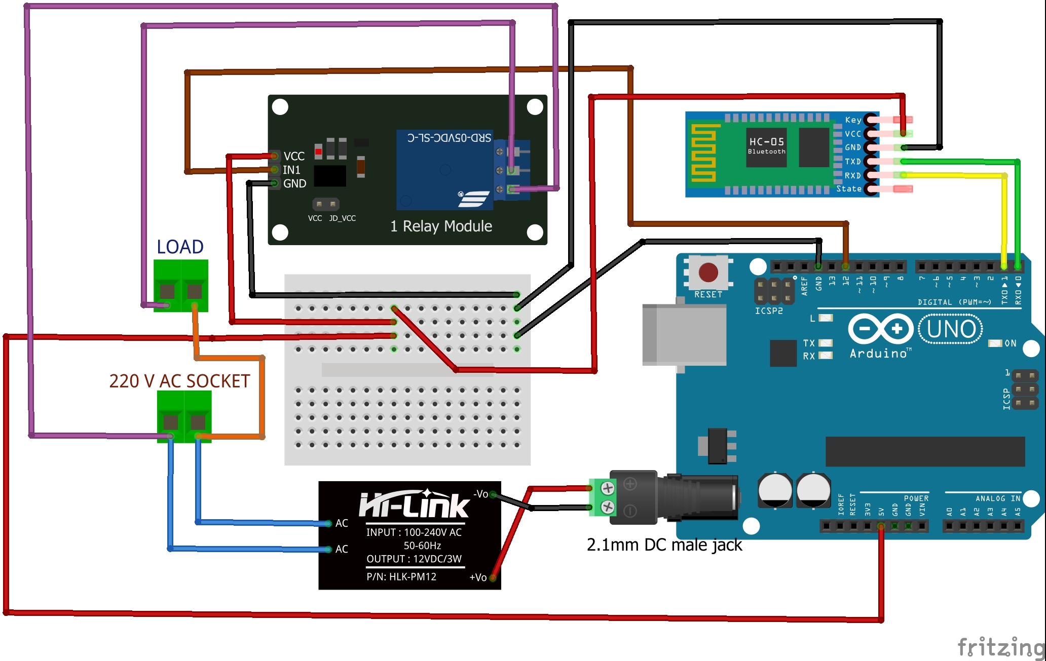
A combination of circuit diagram and block diagram has been provided as conveniently as possible to help the makers understand the physical configuration and connection of the components. Tables for pin-out of the components is also provided to make things easier. In the project pictures shown here, a handmade relay module has been used but it is suggested to use a ready to use relay module to keep things neat. Also in this project, separate wall outlets have been used to power the Arduino and load. But one can combine them into one by following the provide circuit diagram.
Coming to the programming, there is no need to use include any separate library to write the program successfully. The default layout for an Arduino sketch works just fine. In the first part of the program the necessary variables are created and assigned. In the setup part the output pin is fixed, the output value is initialized and the baud rate for the Bluetooth module is set. In the final body of the sketch the conditions of operation along with relevant changes on the smartphone interface are worked out. Comment line are also provide in the program to provide the makers with a better understanding of the code.
NOTE:- Make sure you disconnect the TXand RX pin of the HC-05 from the Arduino while uploading the code.
Construction and Testing
In the prototype, the components have been kept modular and connected using jumper wires instead of soldering. This not only allows easy troubleshooting and repairing but also makes the assembly process hassle free. It is recommended to make a protective case before using to prevent unsolicited accidents to the users and damage to the device itself (3D printing the parts will allow you to keep things neat and sturdy). This particular prototype has been used at stretch without fail for 10-12 hours and has been in working condition for over a year proving it to be reliable and efficient to say the least
Conclusion
The practical potential is huge as it is standalone rather than a dedicated device. It will be helpful to people with physical disabilities related to restricted motion.Finally I would like to mention that this project is an outcome of curiosity, desire to solve society’s problems through technology and last but not the least for the fun of making cool things.
To buy electronics parts order them from UTSOURCE
Bibliography
· Google.com
· Arduino.cc
By:-
Debanjan Bakshi
M.Tech Applied Electronics and Instrumentation
S.T.E.A.M. Educator and Owner at


Vision Education
Contact no. - 9432013960
Whatsapp no. – 8240526721
Email id – /
| × | 1 | ||||
| × | 1 | ||||
| × | 1 | ||||
| × | 1 | ||||
| × | 1 | ||||
| × | 1 | ||||
| × | 1 | ||||
| × | 1 |

SMARTPLUG USING ARDUINO UNO AND HC-05BLUETOOTH MODULE
Introduction
With the advent of technology things around us are getting ‘smarter’ every day. We can call this the age of smart devices. But most of the smart devices are quite costly at the moment. So, in this project I have come up with a simple idea which will enable you to switch on and off any AC electrical device remotely with your smartphone.
Parts List
1. Arduino UNO/GENUINO development board
2. HC-05 Bluetooth Module
3. 5V Relay Module
4. AC Plug and Socket
5. 12 V DC adapter(to power the Arduino)
6. Jumper wires(M-M and M-F)
7. USB A to B for programming theArduino
Description and Working
Since this project is based on serial communication, no sensors have been used here thereby keeping the production cost low. The Bluetooth HC-05 module used here communicate with both Arduino through wired connection and the smartphone wirelessly. The smartphone provides the input to the Bluetooth module and the module in turn provides an input to the Arduino. Thus it can be said the Bluetooth acts as a mediator between the Arduino and the smartphone. The relay works as the actuator here and is connected to a socket such that it can ON and OFF any device which is connected to the socket making it very robust. The project can also be made with ESP module but it has been mentioned before, our motive was to keep the project economical so we used Bluetooth instead. You can use any smartphone app that can control HC-05 Bluetooth module such as ‘Bluetooth Terminal HC-05’ by ‘mightyIT Communication’ or you can use the ‘.apk’ file provided here which I created through MIT App Inventor.
Circuit and Programming
A combination of circuit diagram and block diagram has been provided as conveniently as possible to help the makers understand the physical configuration and connection of the components. Tables for pin-out of the components is also provided to make things easier. In the project pictures shown here, a handmade relay module has been used but it is suggested to use a ready to use relay module to keep things neat. Also in this project, separate wall outlets have been used to power the Arduino and load. But one can combine them into one by following the provide circuit diagram.
Coming to the programming, there is no need to use include any separate library to write the program successfully. The default layout for an Arduino sketch works just fine. In the first part of the program the necessary variables are created and assigned. In the setup part the output pin is fixed, the output value is initialized and the baud rate for the Bluetooth module is set. In the final body of the sketch the conditions of operation along with relevant changes on the smartphone interface are worked out. Comment line are also provide in the program to provide the makers with a better understanding of the code.
NOTE:- Make sure you disconnect the TXand RX pin of the HC-05 from the Arduino while uploading the code.
Construction and Testing
In the prototype, the components have been kept modular and connected using jumper wires instead of soldering. This not only allows easy troubleshooting and repairing but also makes the assembly process hassle free. It is recommended to make a protective case before using to prevent unsolicited accidents to the users and damage to the device itself (3D printing the parts will allow you to keep things neat and sturdy). This particular prototype has been used at stretch without fail for 10-12 hours and has been in working condition for over a year proving it to be reliable and efficient to say the least
Conclusion
The practical potential is huge as it is standalone rather than a dedicated device. It will be helpful to people with physical disabilities related to restricted motion.Finally I would like to mention that this project is an outcome of curiosity, desire to solve society’s problems through technology and last but not the least for the fun of making cool things.
To buy electronics parts order them from UTSOURCE
Bibliography
· Google.com
· Arduino.cc
By:-
Debanjan Bakshi
M.Tech Applied Electronics and Instrumentation
S.T.E.A.M. Educator and Owner at
Vision Education
Contact no. - 9432013960
Whatsapp no. – 8240526721
Email id – /