Tri-Mode Digital Clock with ATtiny85 and RTC © CC BY-NC-ND
DESCRIPTION
- Introduction
This is my first project using ATtiny85 microcontroller and also including a Real Time Clock (RTC) working with it.
The use of ATtiny85 is a very interesting way to shrink your Arduino projects in a final tiny version.
The Three-Modes Digital Clockincludes a version with common decimal clock and also with two versions of binary clock.
One version of binary clock is traditional where each digit of hours and minutes are converted into binary for a LED display of 7 segments.
The last one is my favorite of an unusual version of binary clock where the first digit represents the hour, the second, the minutes and the third the seconds.
An interesting additional feature is about the use of internal memory of RTC that you can save the status of the mode of clock.
This feature is less known and is not applied commonly but give you an extra bonus card for your projects.
Let's see the project!


- Material List


You will need for this project:
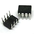
- ATtiny85 microcontroller
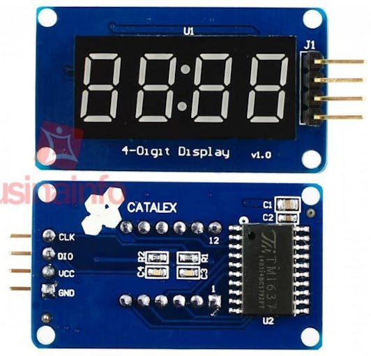
- Display TM1637 (4 Digits x 7 Segments)
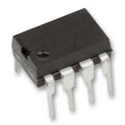
- RTC module (DS1307)
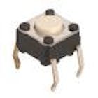
- Tactile button switch
- Breadboard
- Wires
- Power supply (3V to 5V)
Note:
You can use AA batteries (02x or 03x), for example, or any power supply of 5 Volts at maximum.
- Schematics & Program

Programming ATtiny
Many programs of Arduino can be loaded to ATtiny, but in some situations you need an specific library to work on it.
In this project I needed to update the Wire library (support of I2C communications) to TinyWireM library.
With this library you can normally use the DS1307RTC.
- ATtiny85


Basic information about ATtiny
The ATtiny has 5 pins/ports to be used as digital, analogic or PWM as shown on diagrams.
The reset Pin#1 works as Reset and it can also be used as additional port, but you need to setup it with care using specific programs to manage the internal fuses and configuration of the microcontroller.
There are many information about ATtiny85 available on Internet and also tutorials.
With these information you will learn the steps to configure the Arduino to setup the first time the ATtiny.
At first time you will burn the fuses of ATtiny to set the clock (internal or external and the speed) and will also load the bootloader.
Take a look on these instructions:
Note: I did my own version of ATtiny programming shield for Arduino UNO as you can see in the pictures.


- Loading program into ATtiny
To load a program to ATTiny using Arduino as ISP you just need follow these steps:
- Load the program ArduinoISP into Arduino.
- Change the board on Arduino as ATTiny, set the processor as ATtiny85 and set the clock as 8 MHz (internal) according the first setup of microcontroller.
- Load to Arduino the program that you want to transfer to ATtiny.
- Compile and load the program to ATtiny
- Using
The clock is very simple to be used.
Each time you turn on the clock or you press the push button switch, the clock mode will be moved to the next status.
Tri-Modes of the clock:
- Mode 1: Digital / Decimal digits
This is the traditional mode showing hours and minutes with direct reading.

- Mode 2: Binary #1 (digits of hours and minutes are coded to binary)
In this mode you can see each decimal digit converted into its binary corresponding number as follows:
Segments x Decimal Values:
A = 0 / B = 1 / C = 2 / D = 4 / E = 8 / F = 16 / G = 32 Example:
Time 14:21 hs is:
- 1 = B
- 4 = D
- 2 = C
- 1 = B

- Mode 3: Binary #2 (hours, minutes and seconds coded to binary)
In this mode the calculation is similar to mode 2 but here the hour is coded to binary, also the minutes and the seconds.
Note that in this case we can save two digits to represent hour and minutes.
With this I can include the seconds in the third digit of display and keeping one digit free of usage.
Example:
Time 14:21:29 hs is:
- 14 hours = C + D + E
- 21 minutes = B + D + F
- 29 seconds = B + D + E + F


- Introduction
This is my first project using ATtiny85 microcontroller and also including a Real Time Clock (RTC) working with it.
The use of ATtiny85 is a very interesting way to shrink your Arduino projects in a final tiny version.
The Three-Modes Digital Clockincludes a version with common decimal clock and also with two versions of binary clock.
One version of binary clock is traditional where each digit of hours and minutes are converted into binary for a LED display of 7 segments.
The last one is my favorite of an unusual version of binary clock where the first digit represents the hour, the second, the minutes and the third the seconds.
An interesting additional feature is about the use of internal memory of RTC that you can save the status of the mode of clock.
This feature is less known and is not applied commonly but give you an extra bonus card for your projects.
Let's see the project!
- Material List
You will need for this project:
- ATtiny85 microcontroller
- Display TM1637 (4 Digits x 7 Segments)
- RTC module (DS1307)
- Tactile button switch
- Breadboard
- Wires
- Power supply (3V to 5V)
Note:
You can use AA batteries (02x or 03x), for example, or any power supply of 5 Volts at maximum.
- Schematics & Program
Programming ATtiny
Many programs of Arduino can be loaded to ATtiny, but in some situations you need an specific library to work on it.
In this project I needed to update the Wire library (support of I2C communications) to TinyWireM library.
With this library you can normally use the DS1307RTC.
- ATtiny85
Basic information about ATtiny
The ATtiny has 5 pins/ports to be used as digital, analogic or PWM as shown on diagrams.
The reset Pin#1 works as Reset and it can also be used as additional port, but you need to setup it with care using specific programs to manage the internal fuses and configuration of the microcontroller.
There are many information about ATtiny85 available on Internet and also tutorials.
With these information you will learn the steps to configure the Arduino to setup the first time the ATtiny.
At first time you will burn the fuses of ATtiny to set the clock (internal or external and the speed) and will also load the bootloader.
Take a look on these instructions:
Note: I did my own version of ATtiny programming shield for Arduino UNO as you can see in the pictures.
- Loading program into ATtiny
To load a program to ATTiny using Arduino as ISP you just need follow these steps:
- Load the program ArduinoISP into Arduino.
- Change the board on Arduino as ATTiny, set the processor as ATtiny85 and set the clock as 8 MHz (internal) according the first setup of microcontroller.
- Load to Arduino the program that you want to transfer to ATtiny.
- Compile and load the program to ATtiny
- Using
The clock is very simple to be used.
Each time you turn on the clock or you press the push button switch, the clock mode will be moved to the next status.
Tri-Modes of the clock:
- Mode 1: Digital / Decimal digits
This is the traditional mode showing hours and minutes with direct reading.
- Mode 2: Binary #1 (digits of hours and minutes are coded to binary)
In this mode you can see each decimal digit converted into its binary corresponding number as follows:
Segments x Decimal Values:
A = 0 / B = 1 / C = 2 / D = 4 / E = 8 / F = 16 / G = 32
Example:
Time 14:21 hs is:
- 1 = B
- 4 = D
- 2 = C
- 1 = B
- Mode 3: Binary #2 (hours, minutes and seconds coded to binary)
In this mode the calculation is similar to mode 2 but here the hour is coded to binary, also the minutes and the seconds.
Note that in this case we can save two digits to represent hour and minutes.
With this I can include the seconds in the third digit of display and keeping one digit free of usage.
Example:
Time 14:21:29 hs is:
- 14 hours = C + D + E
- 21 minutes = B + D + F
- 29 seconds = B + D + E + F