Washing Machine Timer © CC BY
DESCRIPTION
Introduction
This is a replacement part for the washing machine I have that has a broken wash timer. The original timer was a mechanical timer/direction switch, which can control the washing tub's motor in following manner:
- Take x minutes of wash time input from user
- Rotate washing tub's motor clockwise for few seconds
- Stop motor for few seconds
- Rotate wash tub's motor anti-clockwise for few seconds
- Stop motor for few seconds
- Keep doing last 4 steps until wash timer expires
I am going to build an electronic timer that can do the same operation.
Demo
Following video demonstrates the operation of this electronic timer:
Hardware
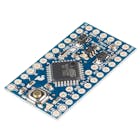
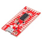
- Arduino Pro Mini: Runs code and controls everything
- 1306 OLED: Show user instruction and timer countdown
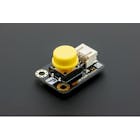
- Red/Black Push Button: Set timer and start timer
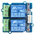
- 5V Relay Modules: Supply AC power to motor and control direction
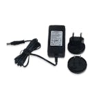
- 5V Adapter: Power the electronic timer
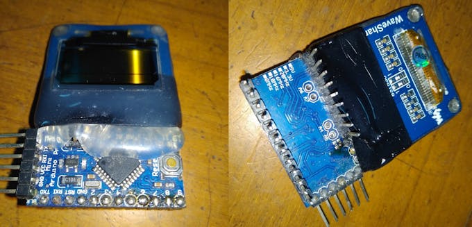
1306 OLED is directly soldered on the pro mini like this:
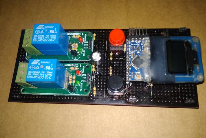
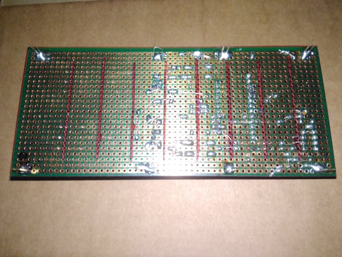
2 relays module, 2 push buttons, Arduino Pro Mini + 1306 OLED is connected on a protoboard like this -
Programming
Step 1: Get a HC-05 Bluetooth-Serial module and change it's baud rate to 57600 according to this tutorial or this step. To perform this step another Arduino Uno or a USB to Serial module will be required.
Use following AT commands
AT
AT+UART = 57600,0,0
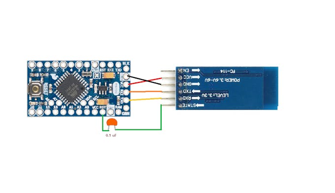
AT+RESETStep 2: After the baud rate is changed to 57600, connect the HC-05 to Arduino pro mini according to following wiring diagram
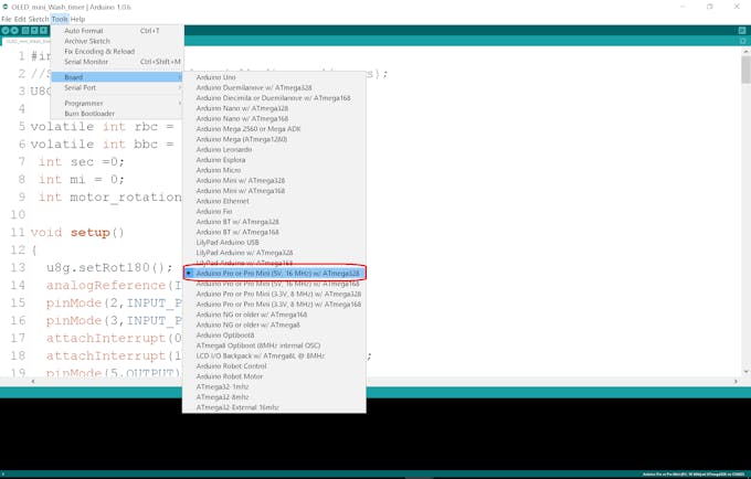
Step 3: Select board from Arduino IDE, paste the code and click upload.
I am using Bluetooth serial, because it enables wireless in system field programmable capabilities, which helped updating the code on pro mini if needed.
Wiring and Device Operation Explained
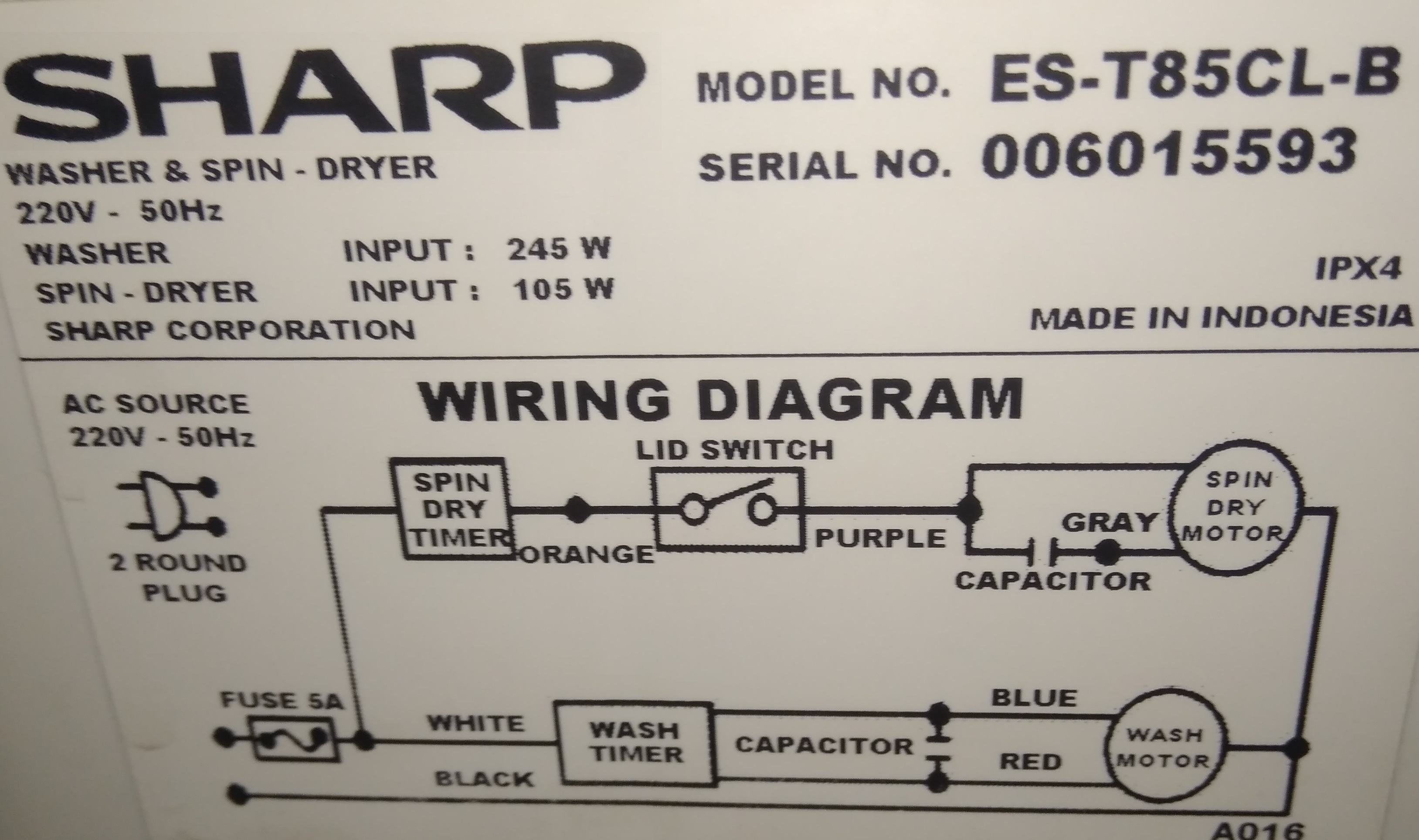
Wiring may vary for newer/different washing machine models, so I am going to explain about my one. Pay attention to the "Sharp" diagram on bottom-right corner, one WHITE WIRE is coming from mains and going to the wash timer, one RED WIRE and one BLUE WIRE is coming out of the wash timer. I have disconnected these 3 wires from the original (faulty) wash timer and brought out through a hole on the top of the washing machine.
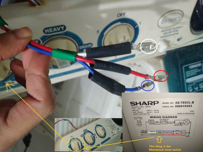
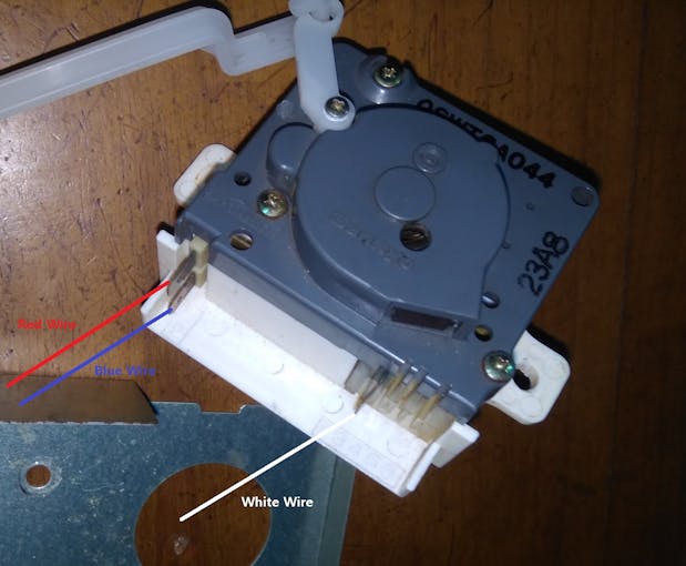
When WHITE WIRE is switched to the RED WIRE motor rotates in clockwise and when WHITE WIRE is switched to the BLUE WIRE motor rotates in anticlockwise direction.
This electronic timer made with Arduino pro mini will keep track of wash time, rotate the wash tub's motor in one direction for 5 seconds by connecting WHITE and RED wires through one relay contact. Then it will stop the motor and wait for 5 seconds. After that it will rotate the was tub's motor in the other direction for 5 seconds by connecting the WHITE and BLUE wires through the other relay contact. Then it will stop and wait for another 5 seconds. All these timing sequence can be modified from the code if necessary.
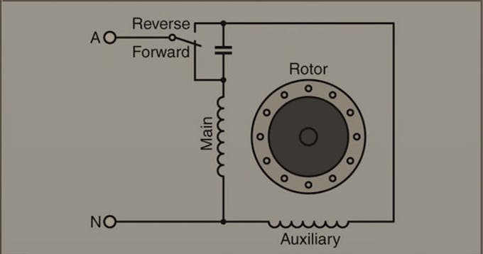
Following diagram shows how just flipping the AC incoming mains to one leg or the other leg of the motor's capacitor, direction of the AC motor can be altered.
Single phase induction motor theory
References
You can learn more in details about each components in these tutorials:
Disclaimer!
This project deals with AC mains supply, do at your own risk !


Introduction
This is a replacement part for the washing machine I have that has a broken wash timer. The original timer was a mechanical timer/direction switch, which can control the washing tub's motor in following manner:
- Take x minutes of wash time input from user
- Rotate washing tub's motor clockwise for few seconds
- Stop motor for few seconds
- Rotate wash tub's motor anti-clockwise for few seconds
- Stop motor for few seconds
- Keep doing last 4 steps until wash timer expires
I am going to build an electronic timer that can do the same operation.
Demo
Following video demonstrates the operation of this electronic timer:
Hardware
- Arduino Pro Mini: Runs code and controls everything
- 1306 OLED: Show user instruction and timer countdown
- Red/Black Push Button: Set timer and start timer
- 5V Relay Modules: Supply AC power to motor and control direction
- 5V Adapter: Power the electronic timer
1306 OLED is directly soldered on the pro mini like this:
2 relays module, 2 push buttons, Arduino Pro Mini + 1306 OLED is connected on a protoboard like this -
Programming
Step 1: Get a HC-05 Bluetooth-Serial module and change it's baud rate to 57600 according to this tutorial or this step. To perform this step another Arduino Uno or a USB to Serial module will be required.
Use following AT commands
AT
AT+UART = 57600,0,0
AT+RESET
Step 2: After the baud rate is changed to 57600, connect the HC-05 to Arduino pro mini according to following wiring diagram
Step 3: Select board from Arduino IDE, paste the code and click upload.
I am using Bluetooth serial, because it enables wireless in system field programmable capabilities, which helped updating the code on pro mini if needed.
Wiring and Device Operation Explained
Wiring may vary for newer/different washing machine models, so I am going to explain about my one. Pay attention to the "Sharp" diagram on bottom-right corner, one WHITE WIRE is coming from mains and going to the wash timer, one RED WIRE and one BLUE WIRE is coming out of the wash timer. I have disconnected these 3 wires from the original (faulty) wash timer and brought out through a hole on the top of the washing machine.
When WHITE WIRE is switched to the RED WIRE motor rotates in clockwise and when WHITE WIRE is switched to the BLUE WIRE motor rotates in anticlockwise direction.
This electronic timer made with Arduino pro mini will keep track of wash time, rotate the wash tub's motor in one direction for 5 seconds by connecting WHITE and RED wires through one relay contact. Then it will stop the motor and wait for 5 seconds. After that it will rotate the was tub's motor in the other direction for 5 seconds by connecting the WHITE and BLUE wires through the other relay contact. Then it will stop and wait for another 5 seconds. All these timing sequence can be modified from the code if necessary.
Following diagram shows how just flipping the AC incoming mains to one leg or the other leg of the motor's capacitor, direction of the AC motor can be altered.
Single phase induction motor theory
References
You can learn more in details about each components in these tutorials:
Disclaimer!
This project deals with AC mains supply, do at your own risk !