7-Segment Clock with Arduino Nano + DS3231 + LDR © LGPL
DESCRIPTION
Intro
In times where you always have a clock on your wrist, be it a watch on your wrist or a smartphone, the Arduino Uno/Nano is a bit dull. You otherwise have NTP server synchronized devices in this article outside, which are constantly online via your Internet connection.
Story
One of my friends refused for personal reasons a device with WiFi connection in his bedroom and so I have the Arduino equipped with a separate clock.
Choose the right product
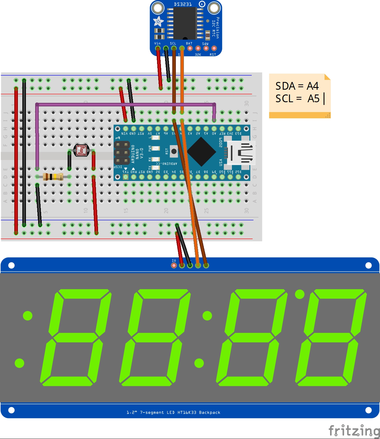
I was surprised how many different products even Adafruit had available: depending on the desired tension, as well as with different precision! Here I decided for two products: the cheaper DS1307 and the probably more precise DS3231.
To be clear: both products can be used in this clock. To use the DS1307, pay attention to the correct PIN assignment and the restriction to the temperature display option: remark "//" the displayTemp(); function within the loop().
Adapt the sketch
I went looking for a sketch and found something with another member. I restructured and fit this sketch, but kept its Czech comments and added English remarks.
The ad was supposed to be as big as possible and so I decided on a 7-segment ad: after all, I only wanted to have the time in mind.
The next positive surprise I experienced while reviewing the sketches: here, the DS3231 provides the option to use the temperature, which the DS1307 - in addition to its inaccuracy - missing.
Init the Clocks
If you have a CR1220 button cell battery, you can follow Adafruit's short tutorial on setting up the clocks. In summary, the time is not downloaded from the Internet, but over time from the local PC. The upload timestamp is transferred to the timers.
Functions
Afterwards I added the LED matrix to the circuit for time and temperature output. The period for the change of time and temperature can be set via variables.
In particular, how the control of the individual - flashing - dots and digits on the LED matrix works and is controlled, is well described in the sketch.
Here I refer to more Adafruit sources.
The sketch is rounded off by the adjustment of summer/winter time and the brightness of the LED matrix depending on the ambient light (at night the display should be darker than in daylight).
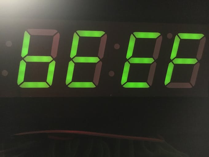
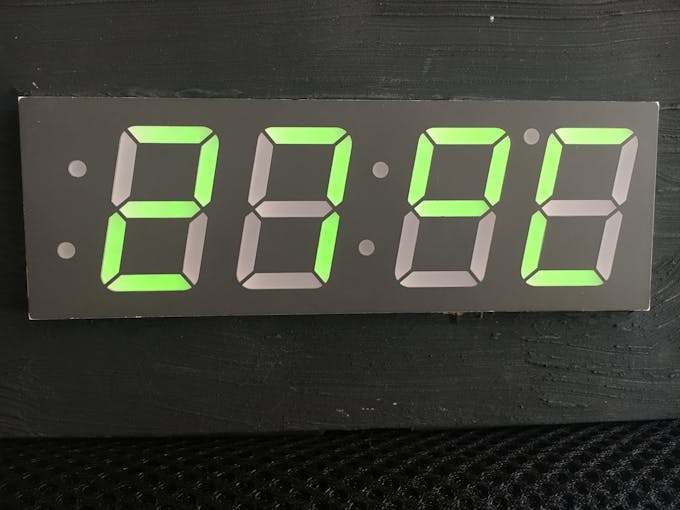
In the video, you certainly noticed the change of time and temperature. Did you pay attention to the point on the left in the picture? This changes its position (up or down) depending on the seconds.
Give me feedback if you know how to issue an "ERR" on the LED matrix in case of failure of the clock. At the moment "bEEF" will appear:
   // oh no, no data!
     Serial.println("DS3231 Sensor Error - cant read temperature");
     matrix.print(0xBEEF, HEX); // inform the user with BEEF
     matrix.writeDisplay();
     delay(5000);
Expansion
An alarm or alarm time is also not integrated yet.
Possibly also succeeds an extension via Bluetooth module and Blynk.
Update 01.02.2019:
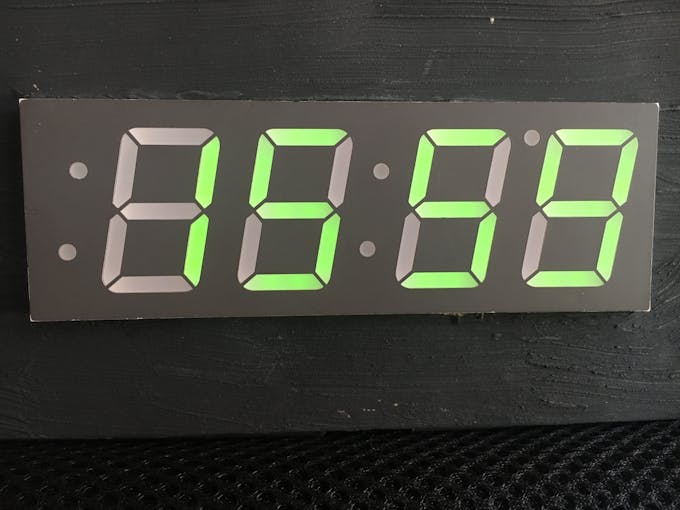
The transfer from the breadboard to a permanent bet on a punch card has been completed today. A few pictures for those interested:


You will find an updated code v1.1 in the attachment as well as a customized frizing image.
 |
| × | 1 | |||
| × | 1 | ||||
| × | 1 | ||||
| × | 1 | ||||
 |
| × | 1 | |||
 |
| × | 1 | |||
 |
| × | 1 | |||
 |
| × | 1 | |||
| × | 1 |

Intro
In times where you always have a clock on your wrist, be it a watch on your wrist or a smartphone, the Arduino Uno/Nano is a bit dull. You otherwise have NTP server synchronized devices in this article outside, which are constantly online via your Internet connection.
Story
One of my friends refused for personal reasons a device with WiFi connection in his bedroom and so I have the Arduino equipped with a separate clock.
Choose the right product
I was surprised how many different products even Adafruit had available: depending on the desired tension, as well as with different precision! Here I decided for two products: the cheaper DS1307 and the probably more precise DS3231.
To be clear: both products can be used in this clock. To use the DS1307, pay attention to the correct PIN assignment and the restriction to the temperature display option: remark "//" the displayTemp(); function within the loop().
Adapt the sketch
I went looking for a sketch and found something with another member. I restructured and fit this sketch, but kept its Czech comments and added English remarks.
The ad was supposed to be as big as possible and so I decided on a 7-segment ad: after all, I only wanted to have the time in mind.
The next positive surprise I experienced while reviewing the sketches: here, the DS3231 provides the option to use the temperature, which the DS1307 - in addition to its inaccuracy - missing.
Init the Clocks
If you have a CR1220 button cell battery, you can follow Adafruit's short tutorial on setting up the clocks. In summary, the time is not downloaded from the Internet, but over time from the local PC. The upload timestamp is transferred to the timers.
Functions
Afterwards I added the LED matrix to the circuit for time and temperature output. The period for the change of time and temperature can be set via variables.
In particular, how the control of the individual - flashing - dots and digits on the LED matrix works and is controlled, is well described in the sketch.
Here I refer to more Adafruit sources.
The sketch is rounded off by the adjustment of summer/winter time and the brightness of the LED matrix depending on the ambient light (at night the display should be darker than in daylight).
In the video, you certainly noticed the change of time and temperature. Did you pay attention to the point on the left in the picture? This changes its position (up or down) depending on the seconds.
Give me feedback if you know how to issue an "ERR" on the LED matrix in case of failure of the clock. At the moment "bEEF" will appear:
// oh no, no data!
Serial.println("DS3231 Sensor Error - cant read temperature");
matrix.print(0xBEEF, HEX); // inform the user with BEEF
matrix.writeDisplay();
delay(5000);
Expansion
An alarm or alarm time is also not integrated yet.
Possibly also succeeds an extension via Bluetooth module and Blynk.
Update 01.02.2019:
The transfer from the breadboard to a permanent bet on a punch card has been completed today. A few pictures for those interested:
You will find an updated code v1.1 in the attachment as well as a customized frizing image.
Github